259
12.
Frequently Asked Questions
Please check this
for more information. Here we will answer the most common
questions
1 What is the proper way to place the beacons?
-
The actual distance between beacons must be
≤ 30m.
Provide the line
of sight from one beacon to minimum two others
2 How far can beacons be located from modem?
-
In the open space the distance from the modem to the beacon can reach
several hundred meters
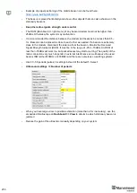
3 What if hedgehog shown as
orange
circle or
inside
in the Dashboard?
-
Blue
- normal mode and confident tracking
-
Orange
- system provides the best location data possible, but
confidence is lower, than blue
-
transparent
- lost radio packets or no ultrasound coverage
4 What is the obstacle for ultrasound?
-
The real obstacles for ultrasound are walls (concrete), glass, metal. If
you need to cover a multiple-floor territory you can use our Submap
feature in which case the tracking will not be interrupted
5 How the system works in very low and very high temperatures?
-
System is designed for normal office-like conditions and temperatures 0
º
С
- 40 º
С
-
You can see some other types of beacon (outdoor, explosion safe, etc.)
in the
-
We also possible to produce some special versions, which will suit your
case. Please write to
6 Are beacons resistant to explosions, dust, dirt, water, noise?
-
- Low-frequency noise (motor noise, industrial equipment) does not
interfere with the normal operation of the system
-
You can see some other types of beacon (outdoor, explosion safe, etc.)
in the
7 What is the time of delay between positioning the object and
respond?
-
The delay is directly proportional to the update rate. For example, if
update rate is 16 Hz delay is 1.2:1.5x60ms
-
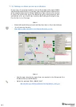
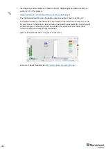
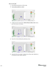
The limit is 1.5x times the maximum distance between the stationary
beacons. To expand the service area, please follow the instructions
shown in the attached screenshot. Notice that positioning the mobile
Summary of Contents for IA-04-2D-Badge
Page 1: ...Marvelmind Indoor Navigation System Operating manual v2022_08_24 www marvelmind com ...
Page 21: ...21 Beacon Mini TX Beacon Industrial RX Beacon Industrial TX Metal ...
Page 22: ...22 Industrial Super Beacon Plastic ...
Page 39: ...39 Figure 7 One External Microphone connection Figure 8 Two External Microphone connection ...
Page 44: ...44 Figure 3 One external microphone soldering Figure 4 Two external microphones soldering ...
Page 46: ...46 Figure 7 Two External Microphones final view Figure 8 Two External Microphones final view ...
Page 118: ...118 6 6 28 The system is now fully operational ...
Page 180: ...180 Floor 5 is enabled Floor 4 is enabled ...
Page 190: ...190 Z X ...
Page 207: ...207 Choose color and press OK Color applied Now background matches floorplan ...
Page 214: ...214 9 24 IMU axis positioning Super Beacon IMU axis positions HW v4 9 IMU axis positions ...
Page 215: ...215 Mini TX IMU axis positions Mini RX beacon IMU axis positions ...
Page 219: ...219 Real time player turned on ...
Page 223: ...223 10 2 Beacon HW v4 9 external interface 4x4 pinout top view ...
Page 224: ...224 10 3 Modem HW v4 9 external interface pinout top view ...
Page 232: ...232 If everything done correctly Own IP address will change Static IP settings completed ...
Page 238: ...238 How to change modes Choose hedge Go to Ultrasound TDMA mode Left Click to change ...


