242
11.6. How to Place Beacons
Avoid placing beacons on long sound-conducting objects
This is very rare but may happen under some special circumstances.
The best practice is to place beacons (stationary and mobile) in places that would not
result in the transfer of ultrasound energy from the b
eacon’s board/case directly to the
place it is attached via a medium other than air. For example, solid attachment of a
beacon to a long horizontal metal tube may result in the following:
-
Sound emitted from the beacon propagates directly to the metal tube.
-
Propagation losses inside metal are much smaller than in the air Moreover, the tube
may act as a low-loss waveguide.
-
If the tube is solid enough and long enough, there may be an unusual effect where
the receiving beacon receives the signal sooner than expected, i.e., sooner than the
distance divided by the speed of sound in air. That happens because the speed of
sound in metal is much higher than the speed of sound in the air. The ultrasound
signal may even look stronger than the real signal propagated through the air due to
the lower amount of losses of ultrasonic in metal than in the air.
-
It is good practice to place beacons on something relatively soft or something that
does not conduct sound.
Place beacons in a way that provides the proper ultrasonic coverage. It must be
one beacon in the line of sight of minimum 2 beacons. Try to locate them under
ceilings to avoid shadows, walls etc.
-
Optimal settings for stationary beacons in small and big rooms.
-
Use 30
–50 ultrasonic pulses for larger places and the default 5 pulses for smaller
places.
-
Optimal settings for noisy environment.
There are several ways to reduce impact:
-
Mobile beacons can be placed very close to the source of noise without
harm, but stationary beacons should be placed further from the noise
because they are receiving the ultrasound, whereas the mobile beacon is
emitting the ultrasound.
Learn more about placing of the beacons here:
How to increase accuracy of precise
Summary of Contents for IA-04-2D-Badge
Page 1: ...Marvelmind Indoor Navigation System Operating manual v2022_08_24 www marvelmind com ...
Page 21: ...21 Beacon Mini TX Beacon Industrial RX Beacon Industrial TX Metal ...
Page 22: ...22 Industrial Super Beacon Plastic ...
Page 39: ...39 Figure 7 One External Microphone connection Figure 8 Two External Microphone connection ...
Page 44: ...44 Figure 3 One external microphone soldering Figure 4 Two external microphones soldering ...
Page 46: ...46 Figure 7 Two External Microphones final view Figure 8 Two External Microphones final view ...
Page 118: ...118 6 6 28 The system is now fully operational ...
Page 180: ...180 Floor 5 is enabled Floor 4 is enabled ...
Page 190: ...190 Z X ...
Page 207: ...207 Choose color and press OK Color applied Now background matches floorplan ...
Page 214: ...214 9 24 IMU axis positioning Super Beacon IMU axis positions HW v4 9 IMU axis positions ...
Page 215: ...215 Mini TX IMU axis positions Mini RX beacon IMU axis positions ...
Page 219: ...219 Real time player turned on ...
Page 223: ...223 10 2 Beacon HW v4 9 external interface 4x4 pinout top view ...
Page 224: ...224 10 3 Modem HW v4 9 external interface pinout top view ...
Page 232: ...232 If everything done correctly Own IP address will change Static IP settings completed ...
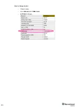
Page 238: ...238 How to change modes Choose hedge Go to Ultrasound TDMA mode Left Click to change ...


