32
3.6.1.
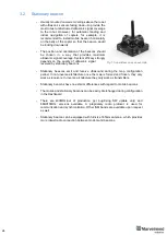
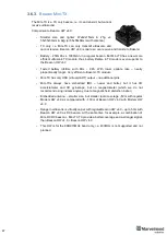
The Super-Beacon is a dual-use beacon
– it can both receive
and transmit ultrasonic pulses.
The Super-Beacon Beacon can be used in both the Non-
Inverse Architecture (NIA) and the Inverse Architecture (IA):
Supports license-free 915MHz ISM band (US) and license-
free SRD band 868MHz (EU). Support of the 433MHz ISM
band (EU) comes with a larger order.
Key features:
-
The Super-Beacon has a separate receiving part with
a single wide-beam microphone and sharp DSP
filters (like Mini-RX or Industrial-RX has). Thus, it is more sensitive, than Beacon
HW v4.9, more resistant to external noise, and easier to setup, because you don’t
have to care about turning on and off ultrasonic sensors in order to optimize
coverage vs. sensitivity
-
The Super-Beacon can receive any ultrasonic frequency from the bands: 19kHz,
22kHz, 25kHz, 28kHz, 31kHz, 34kHz, 37kHz, 45kHz. The filter can be simply
selected in the Dashboard. At the same time, the ultrasonic frequency of Beacon
HW v4.9 is HW-defined by u
ltrasonic sensors and can’t be changed
-
The Super-Beacon can receive several ultrasonic frequencies at once. That is used
in the Inverse Architecture. See the
-
The Super-Beacon has several-times improved battery lifetime in TX mode as
compared with Beacon HW v4.9
-
The Super-Beacon can work with regular Beacons HW v4.9 and Mini-RX and
Industrial-RX in any combination as a part of a Starter Set or as a part of navigation
systems. In all cases, beacons shall use the same radio band
Super-Beacon also has outdoor (IP54) version
, which is protected from dust and water
Demo video:
Demo: IP56 testing of Super-Beacon-IPxx
Figure 1: Outdoor version (IP54)
Summary of Contents for IA-04-2D-Badge
Page 1: ...Marvelmind Indoor Navigation System Operating manual v2022_08_24 www marvelmind com ...
Page 21: ...21 Beacon Mini TX Beacon Industrial RX Beacon Industrial TX Metal ...
Page 22: ...22 Industrial Super Beacon Plastic ...
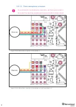
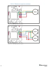
Page 39: ...39 Figure 7 One External Microphone connection Figure 8 Two External Microphone connection ...
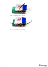
Page 44: ...44 Figure 3 One external microphone soldering Figure 4 Two external microphones soldering ...
Page 46: ...46 Figure 7 Two External Microphones final view Figure 8 Two External Microphones final view ...
Page 118: ...118 6 6 28 The system is now fully operational ...
Page 180: ...180 Floor 5 is enabled Floor 4 is enabled ...
Page 190: ...190 Z X ...
Page 207: ...207 Choose color and press OK Color applied Now background matches floorplan ...
Page 214: ...214 9 24 IMU axis positioning Super Beacon IMU axis positions HW v4 9 IMU axis positions ...
Page 215: ...215 Mini TX IMU axis positions Mini RX beacon IMU axis positions ...
Page 219: ...219 Real time player turned on ...
Page 223: ...223 10 2 Beacon HW v4 9 external interface 4x4 pinout top view ...
Page 224: ...224 10 3 Modem HW v4 9 external interface pinout top view ...
Page 232: ...232 If everything done correctly Own IP address will change Static IP settings completed ...
Page 238: ...238 How to change modes Choose hedge Go to Ultrasound TDMA mode Left Click to change ...

