14
1.1.
Key capabilities:
Parameter
Technical Specifications
Distance between
beacons
-
Reaches up to 50 meters and up to 100 meters with
under laboratory conditions (Mini-
RX or Super-Beacon to Super-Beacon with RX4 only)
-
Recommended distance is 30 meters (Transducer4 on the first beacon is looking straight at
the Transducer4 on the second beacon, other transducers are switched off)
Coverage area
-
Reaches up to 1000m
2
with the Starter Set configurations
-
Coverage for larger territories is provided using submap
– like cells in cellular networks
Location precision
-
Absolute: 1
–3% of the distance to the beacons
-
Differential precision:
±2cm
Location update
rate
-
1/20Hz to 25Hz (Ultrasonic based only)
-
100Hz with ultr IMU fusion enabled (Only for Beacons HW v4.9-IMU-Discontinued)
-
Can be set manually via Dashboard software
-
Depends on the distance between mobile and stationary beacons (shorter distance
—
higher update rate)
-
Depends on the number of mobile beacons (Non-Inverse Architecture; for Inverse
Architecture no such dependency)
-
Depends on the radio profile (500kbps, 153kbps, 38kbps)
-
Slightly depends on the number of stationary beacons
—dependence is not the same as for
mobile beacons
Power supply
Internal: 1000mAh LiPo battery (Super-Beacon)
-
Battery lifetime: from 2 days to several months depending on the mode of operations
*For other types of beacons look to the
External: micro USB
– recommended for permanent use
Weight
Mobile beacon (Super-Beacon) from the starter set:
-
59 grams (including 1000mAh battery, Super-Beacon housing and 50mm antenna)
-
27 grams (Super-Beacon, bare board w/o battery)
*For other types of beacons look to the
Beacon size
Size: 55x55x33mm (with 50mm antenna: 55x55x65mm) (Super-Beacon)
Summary of Contents for IA-04-2D-Badge
Page 1: ...Marvelmind Indoor Navigation System Operating manual v2022_08_24 www marvelmind com ...
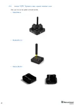
Page 21: ...21 Beacon Mini TX Beacon Industrial RX Beacon Industrial TX Metal ...
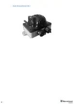
Page 22: ...22 Industrial Super Beacon Plastic ...
Page 39: ...39 Figure 7 One External Microphone connection Figure 8 Two External Microphone connection ...
Page 44: ...44 Figure 3 One external microphone soldering Figure 4 Two external microphones soldering ...
Page 46: ...46 Figure 7 Two External Microphones final view Figure 8 Two External Microphones final view ...
Page 118: ...118 6 6 28 The system is now fully operational ...
Page 180: ...180 Floor 5 is enabled Floor 4 is enabled ...
Page 190: ...190 Z X ...
Page 207: ...207 Choose color and press OK Color applied Now background matches floorplan ...
Page 214: ...214 9 24 IMU axis positioning Super Beacon IMU axis positions HW v4 9 IMU axis positions ...
Page 215: ...215 Mini TX IMU axis positions Mini RX beacon IMU axis positions ...
Page 219: ...219 Real time player turned on ...
Page 223: ...223 10 2 Beacon HW v4 9 external interface 4x4 pinout top view ...
Page 224: ...224 10 3 Modem HW v4 9 external interface pinout top view ...
Page 232: ...232 If everything done correctly Own IP address will change Static IP settings completed ...
Page 238: ...238 How to change modes Choose hedge Go to Ultrasound TDMA mode Left Click to change ...

