95
6.4.5.22. Modem will go to DFU mode. Press
UPGRADE
button in the DfuSe
program
6.4.5.23. After a couple of seconds, the DFU will be uploaded to the modem. Make
sure it takes 1-3 seconds and does not happen immediately. Otherwise,
the SW has not been uploaded correctly. If the DFU appears to upload
immediately, check the "Choose" button you used or change the version
of DfuSe SW to a different one
6.4.5.24. Disconnect the short circuit
6.4.5.25. Start the Dashboard and press
RESET
button
6.4.5.26. If you experience difficulties in DFU programming, please try the
following:
6.4.5.27. Use a different computer with a different version of Windows or another
operating system
6.4.5.28. Install a different DfuSe version (whichever works best with your
Windows)
If you have uploaded the latest firmware for all the boards, you can start to activate the
system:
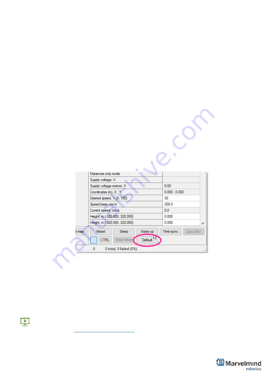
6.4.6. While the beacon or modem is connected to the Dashboard, click the
DEFAULT
button on the Dashboard to upload the default settings
6.4.7.
Write down the beacon’s address for future use or change the address
at
your convenience as shown here. Beacons addresses should not be
repeated.
6.4.8. Press the RESET button on your beacons and modem after programming
6.4.9. After programming devices with the latest software, the modem and beacons
are ready for use
6.4.10. Place the stationary beacons high on the walls vertically in a way that will
provide optimal ultrasonic coverage.
Write down the beacon’s height for future
change in the settings
. The help video on installation can be found here -
Summary of Contents for IA-04-2D-Badge
Page 1: ...Marvelmind Indoor Navigation System Operating manual v2022_08_24 www marvelmind com ...
Page 21: ...21 Beacon Mini TX Beacon Industrial RX Beacon Industrial TX Metal ...
Page 22: ...22 Industrial Super Beacon Plastic ...
Page 39: ...39 Figure 7 One External Microphone connection Figure 8 Two External Microphone connection ...
Page 44: ...44 Figure 3 One external microphone soldering Figure 4 Two external microphones soldering ...
Page 46: ...46 Figure 7 Two External Microphones final view Figure 8 Two External Microphones final view ...
Page 118: ...118 6 6 28 The system is now fully operational ...
Page 180: ...180 Floor 5 is enabled Floor 4 is enabled ...
Page 190: ...190 Z X ...
Page 207: ...207 Choose color and press OK Color applied Now background matches floorplan ...
Page 214: ...214 9 24 IMU axis positioning Super Beacon IMU axis positions HW v4 9 IMU axis positions ...
Page 215: ...215 Mini TX IMU axis positions Mini RX beacon IMU axis positions ...
Page 219: ...219 Real time player turned on ...
Page 223: ...223 10 2 Beacon HW v4 9 external interface 4x4 pinout top view ...
Page 224: ...224 10 3 Modem HW v4 9 external interface pinout top view ...
Page 232: ...232 If everything done correctly Own IP address will change Static IP settings completed ...
Page 238: ...238 How to change modes Choose hedge Go to Ultrasound TDMA mode Left Click to change ...


