37
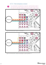
3.6.1.2. Omni microphone schemes
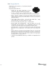
If you don’t want to use 4x4 pinout to connect Omni, use this scheme to solder it.
Be careful: You should have soldering skills to solder Omni Microphone on board
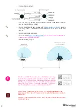
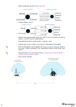
Figure 4: Omni-Microphone connection for Super-Beacon
Figure 5: Omni-Microphone connection for Super-Beacon-2 and Super-Beacon-3
Summary of Contents for IA-04-2D-Badge
Page 1: ...Marvelmind Indoor Navigation System Operating manual v2022_08_24 www marvelmind com ...
Page 21: ...21 Beacon Mini TX Beacon Industrial RX Beacon Industrial TX Metal ...
Page 22: ...22 Industrial Super Beacon Plastic ...
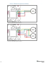
Page 39: ...39 Figure 7 One External Microphone connection Figure 8 Two External Microphone connection ...
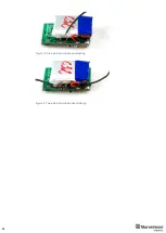
Page 44: ...44 Figure 3 One external microphone soldering Figure 4 Two external microphones soldering ...
Page 46: ...46 Figure 7 Two External Microphones final view Figure 8 Two External Microphones final view ...
Page 118: ...118 6 6 28 The system is now fully operational ...
Page 180: ...180 Floor 5 is enabled Floor 4 is enabled ...
Page 190: ...190 Z X ...
Page 207: ...207 Choose color and press OK Color applied Now background matches floorplan ...
Page 214: ...214 9 24 IMU axis positioning Super Beacon IMU axis positions HW v4 9 IMU axis positions ...
Page 215: ...215 Mini TX IMU axis positions Mini RX beacon IMU axis positions ...
Page 219: ...219 Real time player turned on ...
Page 223: ...223 10 2 Beacon HW v4 9 external interface 4x4 pinout top view ...
Page 224: ...224 10 3 Modem HW v4 9 external interface pinout top view ...
Page 232: ...232 If everything done correctly Own IP address will change Static IP settings completed ...
Page 238: ...238 How to change modes Choose hedge Go to Ultrasound TDMA mode Left Click to change ...


