Physical installation
17
that one bolt passes through each curved slot in the yoke base (see Figure 4). If additional
bolts are required to mount the luminaire safely, pan adjustment range will be reduced.
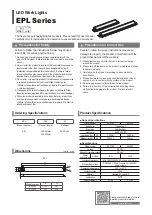
3 . 1 . 3 P o w e r a n d D M X d a t a c a b l e l a y o u t
Figure 5 gives an overview of a suitable cable layout. The dotted lines represent AC
power circuits. The solid lines represent the data link.
13
432
110
Ø247
Figure 4: Mounting yoke attachment points
Figure 5: Schematic cable layout diagram
OPTO-
SPLITTER
Power
230V AC
50 Hz
Power
230V AC
50 Hz
50 Hz
Max. 32 luminaires
or 500m. before
opto-splitter
is required.
OPTO-
SPLITTER
DMX
Universe #1
DMX
Universe #2
Universe #2
AC power
OPTO-
SPLITTER
Power
230V AC
50 Hz
50 Hz
Power
230V AC
50 Hz
Max. 32 luminaires
or 500m. before
opto-splitter
is required.
Max. 32 luminaires
or 500m. before
opto-splitter
is required.
OPTO-
SPLITTER
DMX
Universe #1
Universe #1
DMX
Universe #2
AC power
Summary of Contents for Exterior 1200 Wash
Page 1: ...user manual Exterior 1200 Wash ...
Page 3: ...3 Section 1 Safety ...
Page 9: ...Section 2 Introduction ...
Page 12: ...12 Exterior 1200 Wash user manual ...
Page 13: ...Introduction to the Exterior 1200 Wash 13 Section 3 Installation ...
Page 25: ...Installing a data link 25 Section 4 General ...
Page 30: ...30 Exterior 1200 Wash user manual ...
Page 31: ...General 31 Section 5 Settings and configuration ...
Page 39: ...Luminaire settings 39 Section 6 Stand alone operation ...
Page 49: ...Stand alone operation 49 Section 7 DMX control ...
Page 54: ...54 Exterior 1200 Wash user manual ...
Page 55: ...DMX controller operation 55 Section 8 Service and accessories ...
Page 70: ...70 Exterior 1200 Wash user manual ...
Page 71: ...Accessories 71 Section 9 Reference ...
Page 82: ...Notes ...
Page 83: ......