95
Learning Basic Features
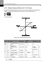
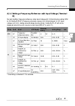
4.2.4 Setting a Frequency Reference with Input Voltage (Terminal
I2)
Set and modify a frequency reference using input voltage at I2 (V2) terminal by setting SW2
to V2. Set the DRV-07 (Frequency reference source) to 4 (V2) and apply 0
–12 V input
voltage to I2 (=V2, Analog current/voltage input terminal). Codes IN-35
–47 will not be
displayed when I2 is set to receive current input (DRV-
07 is set to ‗5‘).
Group Code
Name
LCD Display
Parameter
Setting
Setting Range
Unit
DRV
07
Frequency
reference source
Freq Ref
Src
4
V2
0
–11
-
IN
35
V2 input display
V2 Monitor
0.00
0.00
–12.00
V
37
V2 input filter time
constant
V2 Filter
10
0
–10000
msec
38
Minimum V2 input
voltage
V2 Volt x1
0.00
0.00
–10.00
V
39
Output% at
minimum V2
voltage
V2 Perc y1
0.00
0.00
–100.00
%
40
Maximum V2 input
voltage
V2 Volt x2
10.00
0.00
–10.00
V
41
Output% at
maximum V2
voltage
V2 Perc y2
100.00
0.00
–100.00
%
46
Invert V2 rotational
direction
V2 Inverting 0
No
0
–1
-
47
V2 quantizing level
V2
Quantizing
0.04
0.00*, 0.04
–
10.00
%
*
Quantizing is disabled if ‗0‘ is selected.
Summary of Contents for H100
Page 14: ......
Page 18: ...Preparing the Installation 4 37 90 kW 3 Phase ...
Page 27: ...Preparing the Installation 13 ...
Page 47: ...33 Installing the Inverter ...
Page 48: ...Installing the Inverter 34 Input and Output Control Terminal Block Wiring Diagram ...
Page 61: ...47 Installing the Inverter ...
Page 71: ...Learning to Perform Basic Operations 57 ...
Page 88: ...Learning to Perform Basic Operations 74 ...
Page 103: ...89 Learning Basic Features Code Description V1 Quantizing ...
Page 129: ...115 Learning Basic Features ...
Page 140: ...Learning Basic Features 126 ...
Page 148: ...Learning Basic Features 134 ...
Page 171: ...157 Learning Advanced Features Deceleration dwell operation ...
Page 183: ...169 Learning Advanced Features ...
Page 184: ...Learning Advanced Features 170 PID Command Block ...
Page 185: ...171 Learning Advanced Features PID Feedback Block ...
Page 186: ...Learning Advanced Features 172 PID Output Block ...
Page 187: ...173 Learning Advanced Features PID Output Mode Block ...
Page 197: ...183 Learning Advanced Features ...
Page 201: ...187 Learning Advanced Features Code Description 100 EPID1 Control block ...
Page 202: ...Learning Advanced Features 188 EPID2 Control block ...
Page 237: ...223 Learning Advanced Features Time Period Schedule AP3 38 Except3 Day 01 01 ...
Page 244: ...Learning Advanced Features 230 ...
Page 259: ...245 Learning Advanced Features Code Description Code Description Volt ...
Page 362: ...Learning Protection Features 348 ...
Page 415: ...401 RS 485 Communication Features Item Standards Parity check None ...
Page 524: ...Table of Functions 510 ...
Page 533: ...Table of Functions 519 ...
Page 547: ...533 Troubleshooting ...
Page 585: ...Technical Specification 571 ...
Page 594: ...580 ...
Page 595: ...581 ...
Page 596: ...582 ...


