Learning Advanced Features
300
Group Code Name
LCD Display
Parameter
Setting
Setting Range
Unit
06
Analog output1
monitor
AO1
Monitor
0.0
0.0
–1000.0
%
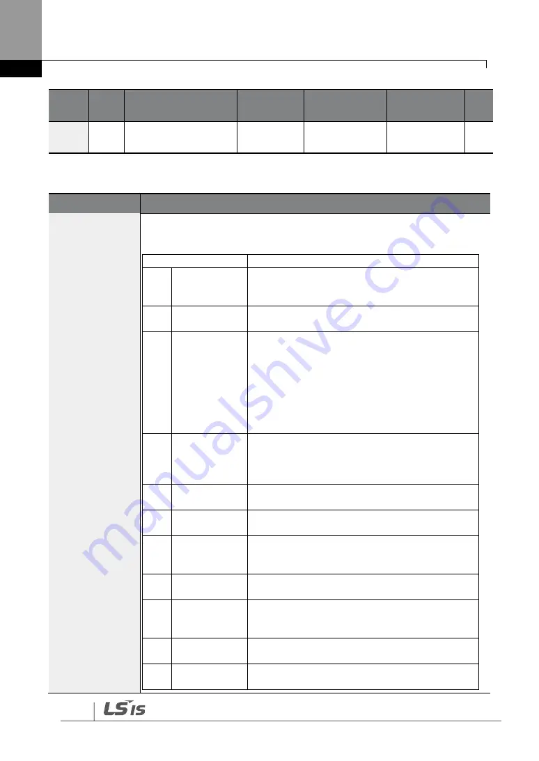
Voltage and Current Analog Output Setting Details
Code
Description
OUT-01 AO1
Mode
Select a constant value for output. The following example for output
voltage setting.
Setting
Function
0
Frequency
Outputs operation frequency as a standard. 10
V output is made from the frequency set at
DRV-20 (Max Freq).
1
Output
Current
10 V output is made from 150% of inverter rated
current.
2
Output
Voltage
Sets the outputs based on the inverter output
voltage. 10 V output is made from a set voltage
in BAS-15 (Rated V).
If 0 V is set in BAS-15, 200 V/400 V models
output
10 V based on the actual input voltages (240 V
and
480 V respectively).
3
DC Link Volt
Outputs inverter DC link voltage as a standard.
Outputs 10 V when the DC link voltage is 410 V
DC for 200 V models, and 820 V DC for 400 V
models.
4
Output Power Monitors output wattage. 150% of rated output
is the maximum display voltage (10 V).
7
Target Freq
Outputs set frequency as a standard. Outputs
10 V at the maximum frequency (DRV-20).
8
Ramp Freq
Outputs frequency calculated with Acc/Dec
function as a standard. May vary with actual
output frequency. Outputs 10 V.
9
PID Ref Value Outputs command value of a PID controller as a
standard. Outputs approximately 6.6 V at 100%.
10
PID Fdk
Value
Outputs feedback volume of a PID controller as
a standard. Outputs approximately 6.6 V at
100%.
11
PID Output
Outputs output value of a PID controller as a
standard. Outputs approximately 10 V at 100%.
12
Constant
Outputs OUT-05 (AO1 Const %) value as a
standard.
Summary of Contents for H100
Page 14: ......
Page 18: ...Preparing the Installation 4 37 90 kW 3 Phase ...
Page 27: ...Preparing the Installation 13 ...
Page 47: ...33 Installing the Inverter ...
Page 48: ...Installing the Inverter 34 Input and Output Control Terminal Block Wiring Diagram ...
Page 61: ...47 Installing the Inverter ...
Page 71: ...Learning to Perform Basic Operations 57 ...
Page 88: ...Learning to Perform Basic Operations 74 ...
Page 103: ...89 Learning Basic Features Code Description V1 Quantizing ...
Page 129: ...115 Learning Basic Features ...
Page 140: ...Learning Basic Features 126 ...
Page 148: ...Learning Basic Features 134 ...
Page 171: ...157 Learning Advanced Features Deceleration dwell operation ...
Page 183: ...169 Learning Advanced Features ...
Page 184: ...Learning Advanced Features 170 PID Command Block ...
Page 185: ...171 Learning Advanced Features PID Feedback Block ...
Page 186: ...Learning Advanced Features 172 PID Output Block ...
Page 187: ...173 Learning Advanced Features PID Output Mode Block ...
Page 197: ...183 Learning Advanced Features ...
Page 201: ...187 Learning Advanced Features Code Description 100 EPID1 Control block ...
Page 202: ...Learning Advanced Features 188 EPID2 Control block ...
Page 237: ...223 Learning Advanced Features Time Period Schedule AP3 38 Except3 Day 01 01 ...
Page 244: ...Learning Advanced Features 230 ...
Page 259: ...245 Learning Advanced Features Code Description Code Description Volt ...
Page 362: ...Learning Protection Features 348 ...
Page 415: ...401 RS 485 Communication Features Item Standards Parity check None ...
Page 524: ...Table of Functions 510 ...
Page 533: ...Table of Functions 519 ...
Page 547: ...533 Troubleshooting ...
Page 585: ...Technical Specification 571 ...
Page 594: ...580 ...
Page 595: ...581 ...
Page 596: ...582 ...


