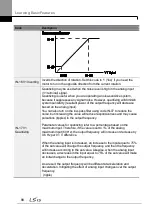
Learning Basic Features
76
Basic Tasks
Description
Ref.
Command source
configuration for RS-485
communication
Configures the inverter to accept communication
signals from upper level controllers, such as PLCs or
PCs.
Motor rotation control
Configures the inverter to limit a motor‘s rotation
direction.
Automatic start-up at
power-on
Configures the inverter to start operating at power-on.
With this configuration, the inverter begins to run and
the motor accelerates as soon as power is supplied to
the inverter. To use automatic start-up configuration,
the operation command terminals at the terminal block
must be turned on.
Automatic restart after reset
of a fault trip condition
Configures the inverter to start operating when the
inverter is reset following a fault trip. In this
configuration, the inverter starts to run and the motor
accelerates as soon as the inverter is reset following a
fault trip condition.
For automatic start-up configuration to work, the
operation command terminals at the terminal block
must be turned on.
Acc/Dec time configuration
based on the Max.
Frequency
Configures the acceleration and deceleration times for
a motor based on a defined maximum frequency.
Acc/Dec time configuration
based on the frequency
reference
Configures acceleration and deceleration times for a
motor based on a defined frequency reference.
Multi-stage Acc/Dec time
configuration using the
multi-function terminal
Configures multi-stage acceleration and deceleration
times for a motor based on defined parameters for the
multi-function terminals.
Acc/Dec time transition
speed (frequency)
configuration
Enables modification of acceleration and deceleration
gradients without configuring the multi-functional
terminals.
Acc/Dec pattern
configuration
Enables modification of the acceleration and
deceleration gradient patterns. Basic patterns to
choose from include linear and S-curve patterns.
Acc/Dec stop command
Stops the current acceleration or deceleration and
controls motor operation at a constant speed. Multi-
function terminals must be configured for this
command.
Linear V/F pattern
operation
Configures the inverter to run a motor at a constant
torque. To maintain the required torque, the operating
Summary of Contents for H100
Page 14: ......
Page 18: ...Preparing the Installation 4 37 90 kW 3 Phase ...
Page 27: ...Preparing the Installation 13 ...
Page 47: ...33 Installing the Inverter ...
Page 48: ...Installing the Inverter 34 Input and Output Control Terminal Block Wiring Diagram ...
Page 61: ...47 Installing the Inverter ...
Page 71: ...Learning to Perform Basic Operations 57 ...
Page 88: ...Learning to Perform Basic Operations 74 ...
Page 103: ...89 Learning Basic Features Code Description V1 Quantizing ...
Page 129: ...115 Learning Basic Features ...
Page 140: ...Learning Basic Features 126 ...
Page 148: ...Learning Basic Features 134 ...
Page 171: ...157 Learning Advanced Features Deceleration dwell operation ...
Page 183: ...169 Learning Advanced Features ...
Page 184: ...Learning Advanced Features 170 PID Command Block ...
Page 185: ...171 Learning Advanced Features PID Feedback Block ...
Page 186: ...Learning Advanced Features 172 PID Output Block ...
Page 187: ...173 Learning Advanced Features PID Output Mode Block ...
Page 197: ...183 Learning Advanced Features ...
Page 201: ...187 Learning Advanced Features Code Description 100 EPID1 Control block ...
Page 202: ...Learning Advanced Features 188 EPID2 Control block ...
Page 237: ...223 Learning Advanced Features Time Period Schedule AP3 38 Except3 Day 01 01 ...
Page 244: ...Learning Advanced Features 230 ...
Page 259: ...245 Learning Advanced Features Code Description Code Description Volt ...
Page 362: ...Learning Protection Features 348 ...
Page 415: ...401 RS 485 Communication Features Item Standards Parity check None ...
Page 524: ...Table of Functions 510 ...
Page 533: ...Table of Functions 519 ...
Page 547: ...533 Troubleshooting ...
Page 585: ...Technical Specification 571 ...
Page 594: ...580 ...
Page 595: ...581 ...
Page 596: ...582 ...


