Ground package before opening”
Before installing the intrusion switch, touch the static-protective package that contains the new intrusion
switch to any unpainted surface on the outside of the server. Then, take the new intrusion switch out of the
package and place them on a static-protective surface.
To install the intrusion switch, complete the following steps:
Watch the procedure
. A video of the installation process is available:
• Youtube:
https://www.youtube.com/playlist?list=PLYV5R7hVcs-Acsjj4tU79GzKnWG316BYn
• Youku:
http://list.youku.com/albumlist/show/id_50483452
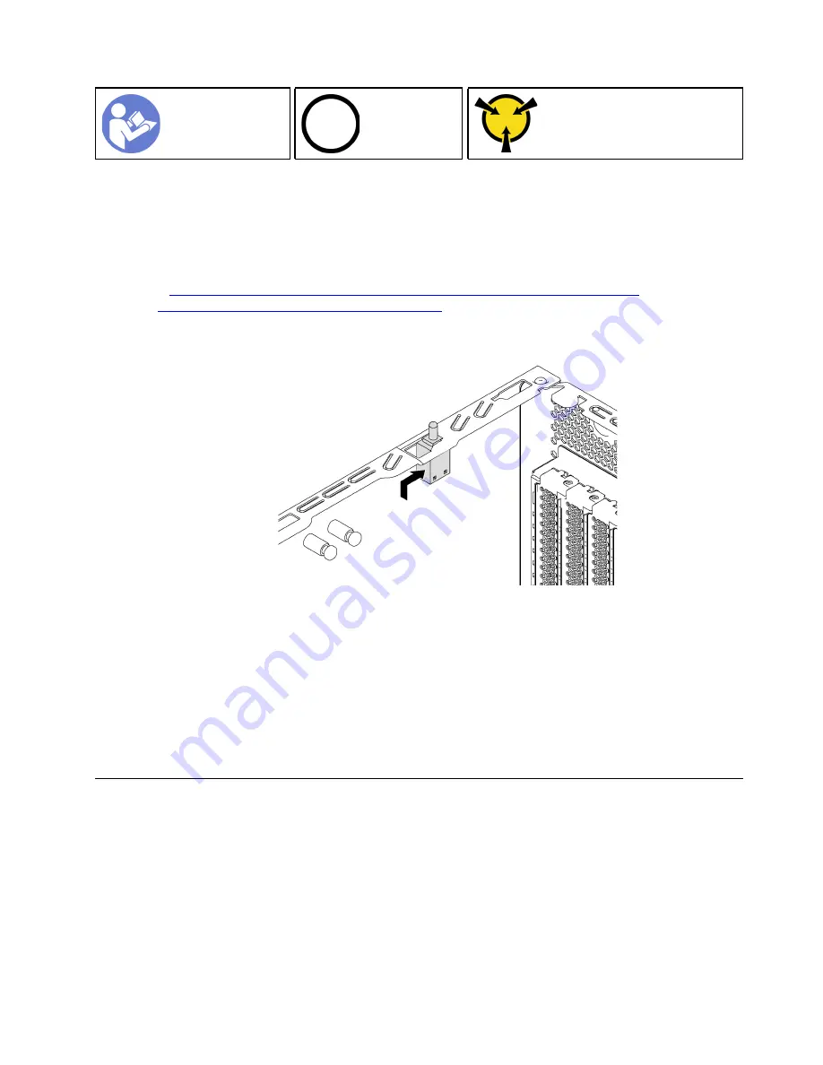
Step 1. Insert the intrusion switch into the chassis and push it in the direction as shown until it is fully
seated.
Figure 104. Intrusion switch installation
Step 2. Connect the cable of the intrusion switch to the intrusion switch connector on the system board.
For the location of the intrusion switch connector, refer to “System board components” on page
24.
After installing the intrusion switch:
1. Install the PCIe adapter retainer. See “Install the PCIe adapter retainer” on page 117.
2. Complete the parts replacement. See “Complete the parts replacement” on page 178.
Fixed power supply replacement
Use this information to remove and install the fixed power supply.
Note:
This section applies only to server models that have a fixed power supply installed.
Remove the fixed power supply
Use this information to remove the fixed power supply.
.
Hardware replacement procedures
135
Summary of Contents for ThinkSystem ST550 7X09
Page 1: ...ThinkSystem ST550 Maintenance Manual Machine Types 7X09 and 7X10 ...
Page 8: ...vi ThinkSystem ST550 Maintenance Manual ...
Page 36: ...28 ThinkSystem ST550 Maintenance Manual ...
Page 188: ...180 ThinkSystem ST550 Maintenance Manual ...
Page 206: ...198 ThinkSystem ST550 Maintenance Manual ...
Page 210: ...202 ThinkSystem ST550 Maintenance Manual ...
Page 219: ......
Page 220: ......


