


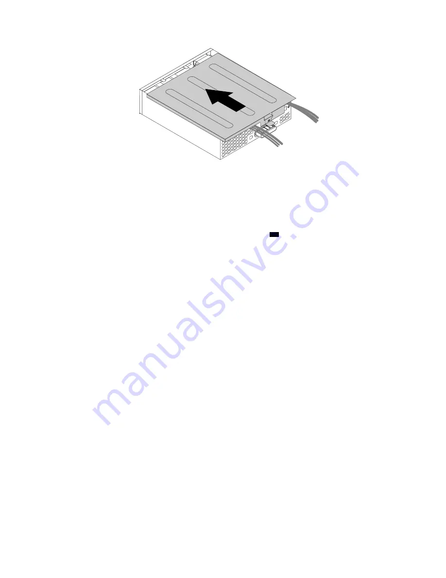
Figure 168. Reinstalling the flex module cover
8. Install the flex module into the flex bay. See “Device in a flex bay” on page 109.
9. Refer to the recorded information about the cable connections and routing. Reconnect all cables
connected to the flex module to the system board. For the front Thunderbolt adapter kit, connect the
cables to the system board and the front Thunderbolt PCIe x4 card as follows:
• Connect the GPIO cable to the Thunderbolt control connector (
47
) on the system board. See “Parts
on the system board” on page 38.
• Connect the internal DP-to-DP cable to the DisplayPort connector on the front Thunderbolt PCIe x4
card.
• Connect the mini-SAS cable to the SAS connector on the front Thunderbolt PCIe x4 card.
• Connect the external DP-to-DP cable to the DisplayPort connector on the front Thunderbolt PCIe x4
card and the DisplayPort connector on the graphics card.
What to do next:
• To work with another piece of hardware, go to the appropriate section.
• To complete the installation or replacement, go to “Completing the parts replacement” on page 210.
VROC upgrade key module
Attention:
Do not open your computer or attempt any repair before reading and understanding the Chapter
1 “Read this first: Important safety information” on page 1.
To remove or install a VROC upgrade key module, do the following:
1. Prepare your computer. See “Preparing your computer and removing the computer cover” on page 103.
2. Remove the direct cooling air baffle. See “Direct cooling air baffle” on page 107.
3. Lay the computer on its side for easier access to the heat-sink-and-fan assembly.
4. To access the VROC upgrade key module, remove the following parts:
• “Direct cooling air baffle” on page 107
• “Power supply assembly” on page 150
• “Front fan assembly” on page 137
• “M.2 solid-state drive holder” on page 140
• “PCIe card retainer” on page 155 (if necessary)
• “Super capacitor module” on page 170 (if necessary)
194
P920 Hardware Maintenance Manual
Summary of Contents for ThinkStation P920
Page 1: ...P920 Hardware Maintenance Manual Machine Types 30BD 30BV and 30BC ...
Page 6: ...iv P920 Hardware Maintenance Manual ...
Page 8: ...vi P920 Hardware Maintenance Manual ...
Page 16: ...8 P920 Hardware Maintenance Manual ...
Page 20: ...12 P920 Hardware Maintenance Manual ...
Page 21: ...1 2 Chapter 1 Read this first Important safety information 13 ...
Page 22: ...14 P920 Hardware Maintenance Manual ...
Page 28: ...20 P920 Hardware Maintenance Manual ...
Page 32: ...24 P920 Hardware Maintenance Manual ...
Page 36: ...28 P920 Hardware Maintenance Manual ...
Page 43: ...Figure 4 Major FRUs and CRUs Chapter 2 Product overview 35 ...
Page 68: ...60 P920 Hardware Maintenance Manual ...
Page 74: ...66 P920 Hardware Maintenance Manual ...
Page 102: ...94 P920 Hardware Maintenance Manual ...
Page 220: ...212 P920 Hardware Maintenance Manual ...
Page 224: ...216 P920 Hardware Maintenance Manual ...
Page 226: ...218 P920 Hardware Maintenance Manual ...
Page 228: ...220 P920 Hardware Maintenance Manual ...
Page 236: ...228 P920 Hardware Maintenance Manual ...
Page 240: ...232 P920 Hardware Maintenance Manual ...
Page 242: ...234 P920 Hardware Maintenance Manual ...
Page 244: ...236 P920 Hardware Maintenance Manual ...
Page 245: ......
Page 246: ......