4. Press the clip underneath the plastic cover of the optical-drive bay so that the cover is ejected out of the
bay. Then, remove the metal shield in the bay.
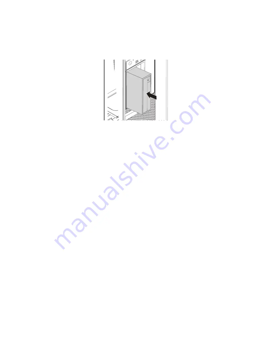
5. Note the orientation of the new optical drive. Then, slide the optical drive into the optical-drive bay from
the front of the chassis until it snaps into position.
Figure 18. Installing the optical drive
6. Connect the cables to the optical drive.
Note:
If you install a flex module or a flex bay storage enclosure, you might need to connect the cables
to the device, a PCI card, or the system board. See “Parts on the system board” on page 35.
7. Reinstall the direct cooling air baffle. See “Direct cooling air baffle” on page 105.
What to do next:
• To work with another piece of hardware, go to the appropriate section.
• To complete the installation or replacement, go to “Completing the parts replacement” on page 213.
Storage drive in the front-access storage enclosure
Attention:
Do not open your computer or attempt any repair before reading and understanding the Chapter
1 “Read this first: Important safety information” on page 1.
You can install or replace a storage drive in the front-access storage enclosure. The storage drive also can be
hot-swappable, which means that you can install or replace the drive without even turning off your computer.
The storage drive in the front-access storage enclosure is hot-swappable only when the following
requirements are met:
• The SATA cable of the front-access storage enclosure is connected to the eSATA connector on the system
board. To verify the cable connection, see “Preparing your computer and removing the computer cover”
on page 101 and “Parts on the system board” on page 35 for more information.
• The operating system of your computer does not reside on the storage drive installed in the front-access
storage enclosure.
Attention:
If any of the above requirements are not met, do not install or replace the storage drive when the
computer is turned on. Otherwise, data on the storage drive might get damaged.
3.5-inch storage drive
To remove or install a 3.5-inch storage drive, do the following:
.
Installing or replacing hardware
109
Summary of Contents for ThinkStation P910
Page 1: ...P910 Hardware Maintenance Manual Machine Types 30B8 and 30B9 ...
Page 14: ...8 P910 Hardware Maintenance Manual ...
Page 18: ...12 P910 Hardware Maintenance Manual ...
Page 19: ...1 2 Chapter 1 Read this first Important safety information 13 ...
Page 20: ...1 2 14 P910 Hardware Maintenance Manual ...
Page 25: ...1 2 Chapter 1 Read this first Important safety information 19 ...
Page 26: ...1 2 20 P910 Hardware Maintenance Manual ...
Page 29: ...Chapter 1 Read this first Important safety information 23 ...
Page 39: ...b f d c e Chapter 2 Product overview 33 ...
Page 52: ...46 P910 Hardware Maintenance Manual ...
Page 64: ...58 P910 Hardware Maintenance Manual ...
Page 84: ...78 P910 Hardware Maintenance Manual ...
Page 98: ...92 P910 Hardware Maintenance Manual ...
Page 106: ...100 P910 Hardware Maintenance Manual ...
Page 224: ...218 P910 Hardware Maintenance Manual ...
Page 226: ...220 P910 Hardware Maintenance Manual ...
Page 228: ...222 P910 Hardware Maintenance Manual ...
Page 236: ...230 P910 Hardware Maintenance Manual ...
Page 240: ...4 Follow the instructions on the screen 234 P910 Hardware Maintenance Manual ...
Page 243: ......
Page 244: ......


