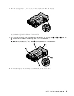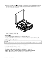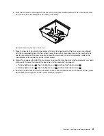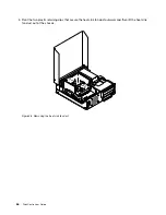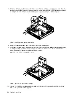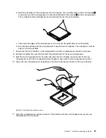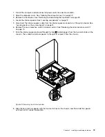
6. Pivot the two plastic retaining clips that secure the heat sink fan duct outward. Then, remove the heat
sink fan duct from the failing heat sink and fan assembly.
Figure 46. Removing the heat sink fan duct
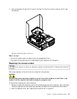
7. Place the new heat sink and fan assembly on the system board so that the four screws are aligned
with the corresponding holes in the system board. Ensure that you properly place the new heat sink
and fan assembly so that you can easily connect the new heat sink and fan assembly cable to the
microprocessor fan connector on the system board.
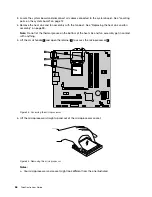
8. Follow this sequence to install the four screws to secure the new heat sink and fan assembly, as shown
in Figure 45 “Screws that secure the heat sink and fan assembly” on page 60:
a. Partially tighten screw
1
, then fully tighten screw
2
, and then fully tighten screw
1
.
b. Partially tighten screw
3
, then fully tighten screw
4
, and then fully tighten screw
3
.
9. Connect the new heat sink and fan assembly cable to the microprocessor fan connector on the system
board. See “Locating parts on the system board” on page 12.
Chapter 5
.
Installing or replacing hardware
61
Summary of Contents for 2934, 2941, 2945, 2961,2982, 2988, 2993, 2996, 3181, 3183, 3185, 3187, 3198, 3202, 3207,ThinkCentre 3209
Page 6: ...iv ThinkCentre User Guide ...
Page 12: ...x ThinkCentre User Guide ...
Page 34: ...22 ThinkCentre User Guide ...
Page 106: ...94 ThinkCentre User Guide ...
Page 140: ...128 ThinkCentre User Guide ...
Page 146: ...134 ThinkCentre User Guide ...
Page 150: ...138 ThinkCentre User Guide ...
Page 154: ...142 ThinkCentre User Guide ...
Page 158: ...146 ThinkCentre User Guide ...
Page 159: ......
Page 160: ......

