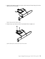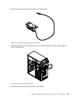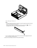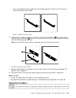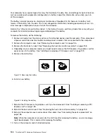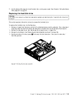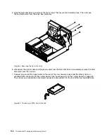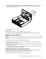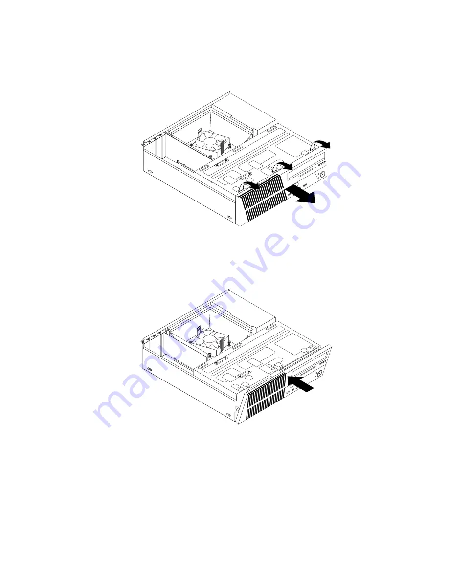
3. Remove the front bezel by releasing the three plastic tabs on the top of the front bezel and pivoting
the front bezel outward to remove it from the computer. Carefully lay the front bezel aside without
disconnecting the power switch and light-emitting diode (LED) assembly cable.
Figure 69. Removing the front bezel
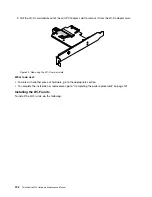
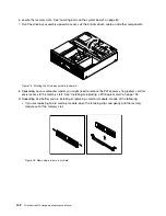
4. To reinstall the front bezel, align the other three plastic tabs on the bottom of the front bezel with the
corresponding holes in the chassis, and then pivot the front bezel inward until it snaps into position.
Figure 70. Reinstalling the front bezel
What to do next:
• To work with another piece of hardware, go to the appropriate section.
• To complete the installation or replacement, go to “Completing the parts replacement” on page 186.
Chapter 10
.
Replacing FRUs (machine types: 10B4, 10B5, 10B6, and 10B7)
137
Summary of Contents for 10AX
Page 6: ...iv ThinkCentre M73 Hardware Maintenance Manual ...
Page 8: ...2 ThinkCentre M73 Hardware Maintenance Manual ...
Page 15: ...Chapter 2 Safety information 9 ...
Page 19: ...Chapter 2 Safety information 13 ...
Page 20: ...1 2 14 ThinkCentre M73 Hardware Maintenance Manual ...
Page 21: ...1 2 Chapter 2 Safety information 15 ...
Page 26: ...1 2 20 ThinkCentre M73 Hardware Maintenance Manual ...
Page 27: ...1 2 Chapter 2 Safety information 21 ...
Page 30: ...24 ThinkCentre M73 Hardware Maintenance Manual ...
Page 34: ...28 ThinkCentre M73 Hardware Maintenance Manual ...
Page 40: ...34 ThinkCentre M73 Hardware Maintenance Manual ...
Page 74: ...68 ThinkCentre M73 Hardware Maintenance Manual ...
Page 92: ...86 ThinkCentre M73 Hardware Maintenance Manual ...
Page 140: ...134 ThinkCentre M73 Hardware Maintenance Manual ...
Page 194: ...188 ThinkCentre M73 Hardware Maintenance Manual ...
Page 248: ...242 ThinkCentre M73 Hardware Maintenance Manual ...
Page 258: ...252 ThinkCentre M73 Hardware Maintenance Manual ...
Page 259: ......
Page 260: ......

