Service Manual JET3
110
Rev. 1.0
3.
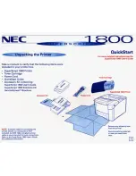
Remove the head cover and press the button
<Jet Adjust>
.
The nozzle seal opens automatically to the
<Jet adjust position>
(4200)
Unfix attachment screws around one rotation with hex key and take off the inside
cover.
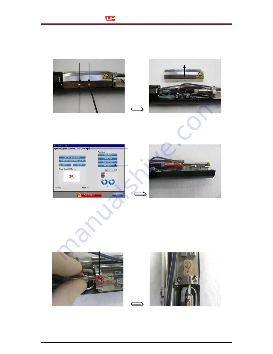
4.
Switch to the tab
<Printhead>
(1) and press button
<Jet Adjust>
(2).
The nozzle seal opens automatically to the
<head adjustment position>
.
1
– Menu <Printhead>
2
–Button <Jet Adjust>
5.
Unfix the right attachment screw of the nozzle retainer just so far that you can adjust
the retainer manhandling. Maybe you need to unfix the second screw as well.
Caution
:
Use the right torx only!
Unfixing
right
attachment screw.
1
2
Summary of Contents for JET3 up
Page 1: ...SERVICE MANUAL ...
Page 12: ...Service Manual JET3 12 Rev 1 0 2 4 Safety sticker Figure 1 ...
Page 58: ...Service Manual JET3 58 Rev 1 0 7 2 Documentations for SK4 Torsional moments for SK4 ...
Page 99: ...Service Manual JET3 Rev 1 0 99 7 3 Documentations for SK6 Torsional moments for SK6 ...
Page 142: ...Service Manual JET3 142 Rev 1 0 ...
Page 144: ...Service Manual JET3 144 Rev 1 0 7 4 Hydraulic 1 Hydraulic scematic ...