


KFU 2-/4-
57
5.6.4
Control terminals – Connection diagrams of configurations
The control hardware and the software of the frequency inverter are freely configur-
able to a great extent. Certain functions can be assigned to the control terminals, and
the internal logic of the software modules can be freely selected.
Thanks to the modular design, the frequency inverter can be adapted to a great range
of different driving tasks.
The demands made of the control hardware and software are well known in the case
of standard driving tasks. This control terminal logic and internal function assignments
of the software modules are available in standard configurations. These assignments
can be selected via parameter
Configuration
30
. The configurations are described in
the following section.
Note:
The KFU 2-/4 units feature the function STO („Safe Torque Off“). If this
function is not required, the “Controller release” signal must be con-
nected to inputs S1IND/STOA and S7IND/STOB.
Inputs S1IND/STOA and S7IND/STOB are connected in series.
Warning!
If the same signal is used for the digital inputs S1IND/STOA and S2IND,
safe disconnection of power supply to the motor according to safety
function STO („Safe Torque Off “) is not guaranteed.
5.7 Configurations
overview
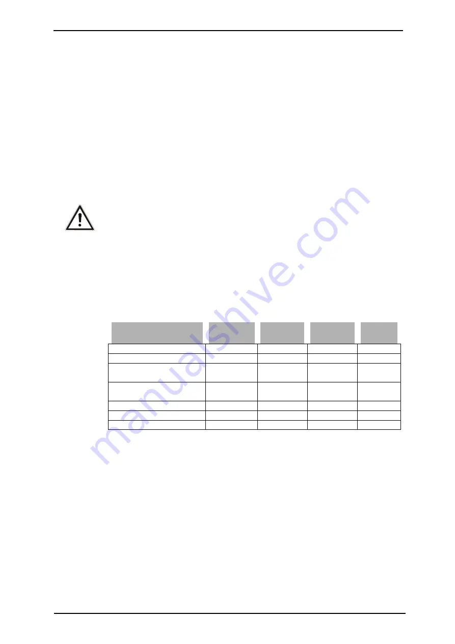
Refer to following table in order to learn which combinations of functions and control
methods are possible. Configurations „Standard“, „Technology Controller“ and „Tor-
que Control“ will be described in the following sections. For configurations „Electronic
Gear“, „Positioning“ and „Brake Control“, please refer to the corresponding applica-
tion manuals.
Configurations:
Function
V/f
Sensorless
vector
Speed con-
trolled
Servo
Standard
110 410 210 510
Technology Controller
111 411 211
Electronic gear with posi-
tion controller
1)
115 415 215 515
Electronic gear + index
controller
1)
116 216
516
Torque control
430
230
530
Positioning
2)
440
240
540
Brake control
3)
160 460 260 560
Please also comply with the following manuals:
1) Application Manual: Electronic Gear, Position Control and Index Control
2) Application Manual: Positioning
3) Application Manual: Lifting Gear Drives and Load Estimation
Note:
The control methods 2xx can be used with
HTL
sensors (with or without
reference track) connected to the basic device or to an extension mod-
ule.
The control methods 2xx with
TTL
sensors require an extension mod-
ule.
An extension module EM-RES for evaluation of resolver signals is re-
quired for operation of a synchronous machine (control method 5xx).


