


KFU 2-/4-
56
5.6.1
External DC 24 V power supply
The bidirectional control terminals X210A.1/ X210A.2 can be used as a voltage output
or voltage input. By connecting an external power supply of DC 24 V ±10% to termi-
nals X210A.1/X210A.2, the function of inputs and outputs as well as the communica-
tion can be maintained.
Requirements to be met by external power supply
Input voltage range
DC 24 V ±10%
Rated input current
Max. 1.0 A (typical 0.45 A)
Peak inrush current
Typical: < 20 A
External fuse
Via standard fuse elements for rated current, charac-
teristic: slow
Safety
Safety extra low voltage (SELV) according to
EN 61800-5-1
Attention!
The digital inputs and the DC 24 V terminal of the electronic control
equipment can withstand external voltage up to DC 30 V. Avoid higher
voltage levels. Higher voltages may destroy the unit.
Note:
Comply with the application manual “Safe Torque Off – STO”, especially
if you apply this safety-related function.
Use suitable external power supply units with a maximum output current of DC 30 V
or use appropriate fuses to protect the unit.
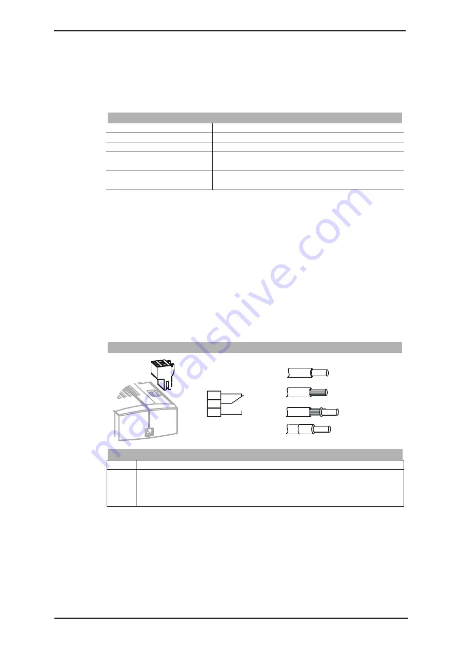
5.6.2 Relay
Output
By default, the freely programmable relay output is linked to the monitoring function
(factory setting). The logic link to various functions can be freely configured via the
software parameters. Connection of the relay output is not absolutely necessary for
the function of the frequency inverter.
Relay Output
1
2
3
0.2 … 1.5 mm
AWG 24 … 16
2
Phoenix ZEC 1,5/3ST5,0
0.2 … 1.5 mm
AWG 24 … 16
2
0.25 … 1.5 mm
AWG 22 … 16
2
0.25 … 1.5 mm
AWG 22 … 16
2
S3OUT
X10
X10
Control terminal X10
Ter.
Description
1 ... 3 Relay output, floating change-over contact, response time approx. 40 ms,
maximum contact load:
make contact: AC 5 A / 240 V, DC 5 A (ohmic) / 24 V
break-contact: AC 3 A / 240 V, DC 1 A (ohmic) / 24 V
5.6.3 Motor
Thermo-Contact
The KFU 2-/4- frequency inverters can evaluate the thermal switch of motor. By de-
fault, terminal X210B.1 (S6IND) is configured as an input for this evaluation. Connect
the thermal switch to the digital input and the DC 24 V supply unit X210A.1. For con-
figuration, refer to sections 12.6 “Motor Temperature” and 14.4.5 “Thermo contact”.


