


TP-6694
9/20
95
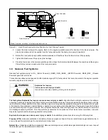
For 180-500 RZXB/REZXB/REZXC/RZXD/REZXD (PSI/ Doosan 11.1L, 14.6L, 18.3L, and 21.9L Engines), use the following:
To change the fuel type, change the wiring harness connections. The engine ECM has fuel tables and spark advance curves
programmed for both natural gas and LPG. Use the following fuel connection lists and wiring diagrams to determine the
applicable connections for your generator set model. Be sure to review the wiring diagram for special applications.
Natural Gas with single fuel valve
Disconnect lead 70E.
Disconnect lead N6.
Disconnect lead N11 (250
– 500 kW only).
Disconnect lead N5.
Disconnect lead 65.
Disconnect lead 65A.
Disconnect lead 73B.
Connect lead 70B2 to fuel valve 1 (FV1), red/black wire.
o
For 250
– 500 kW (14.6 L – 22 L engines),
connect lead 70B2 to fuel valve 1A (FV1A) and lead 70B2A to fuel
valve 1B (FV1B), red/black wires.
Connect lead 73A to fuel valve 1 (FV1), red/white wire.
o
For 250
– 500 kW (14.6 L – 22 L engines),
connect lead 73A to fuel valve 1A (FV1A) and 73A1 to fuel valve 1B
(FV1B), red/white wires.
Connect lead N7 to fuel valve 1 (FV1), green wire.
o
For 250
– 500 kW (14.6 L – 22 L engines),
connect lead N7 to fuel valve 1A (FV1A) and lead N10 to fuel valve
1B (FV1B), green wires.
Connect lead 63 to normally closed (NC), low fuel pressure sensor 1.
Connect lead N3 to common (COM), low fuel pressure sensor 1.
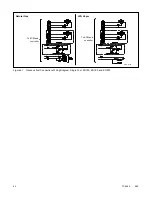
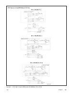
Figure 42
Natural Gas with Single Fuel Valve
Natural Gas
ADV-7968-G
ADV-7994-K
180
– 200 kW (11 L)
250
– 500 kW (14.6 – 22 L)
Summary of Contents for APM402
Page 6: ...6 TP 6694 9 20 ...
Page 16: ...16 TP 6694 9 20 ...
Page 42: ...42 TP 6694 9 20 ...
Page 78: ...78 TP 6694 9 20 ...
Page 112: ...112 TP 6694 9 20 ...
Page 120: ...120 TP 6694 9 20 ...
Page 124: ...124 TP 6694 9 20 Figure 54 20 150 kW Permanent Magnet Single Phase Alternators ADV 5875AB 1 ...
Page 125: ...TP 6694 9 20 125 Figure 55 20 300 kW Permanent Magnet Alternators ADV 5875AB 2 ...
Page 128: ...128 TP 6694 9 20 ...
Page 131: ...TP 6694 9 20 131 Figure 61 Battery Charger to Controller Connections DEC 3000 Controller ...
Page 153: ...TP 6694 9 20 153 Figure 90 Controller Wiring Connections GM78246G 1 ...
Page 154: ...154 TP 6694 9 20 Figure 91 Controller Wiring Connections GM78246G 2 ...
Page 171: ......


