


60
TP-6694
9/20
2.6.2
Modbus® Communications
The controller communicates using Modbus
®
as a slave connection with the Modbus
®
master initiating the communication. The
controller seeks the system and alternator parameters and diagnostic information then responds back to the Modbus
®
master.
In addition, the controller accepts information to alter controller parameters including generator set starting and stopping. See
Figure 25. Refer to the List of Related Materials for available Modbus
®
literature.
Note:
Only one Modbus
®
master can be connected to the controller. Examples include the remote serial annunciator and switchgear
applications
Figure 25
Modbus
®
Connections
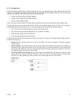
2.7 Reviewing Menu Displays
Use this section to review a summary of the generator set controller data. See Figure 26 or Figure 27 for which menus provide
data monitoring, data adjustments, or require SiteTech
™ software to make data adjustments.
Use the pushbutton/rotary selector dial to navigate to the respective menus.
Menu Name
Controller
Viewable
Controller
Adjustable
SiteTech
Adjustable
Overview
X
Engine Metering
X
Generator Metering
X
GenSet Information
X
X
GenSet Run Time
X
GenSet System
X
X
X
GenSet Calibration
X
X
Voltage Regulation
X
X
X
Digital Inputs
X
X
Digital Outputs
X
X
Analog Inputs
X
X
Event Log
X
Figure 26
Menu Displays for Viewing and Adjusting (DEC3000 Before Firmware Version 3.0.25)
Generator Set
Controller
RS-485
up to 1220 m (4000 ft.)
Modbus
®
Master
Summary of Contents for APM402
Page 6: ...6 TP 6694 9 20 ...
Page 16: ...16 TP 6694 9 20 ...
Page 42: ...42 TP 6694 9 20 ...
Page 78: ...78 TP 6694 9 20 ...
Page 112: ...112 TP 6694 9 20 ...
Page 120: ...120 TP 6694 9 20 ...
Page 124: ...124 TP 6694 9 20 Figure 54 20 150 kW Permanent Magnet Single Phase Alternators ADV 5875AB 1 ...
Page 125: ...TP 6694 9 20 125 Figure 55 20 300 kW Permanent Magnet Alternators ADV 5875AB 2 ...
Page 128: ...128 TP 6694 9 20 ...
Page 131: ...TP 6694 9 20 131 Figure 61 Battery Charger to Controller Connections DEC 3000 Controller ...
Page 153: ...TP 6694 9 20 153 Figure 90 Controller Wiring Connections GM78246G 1 ...
Page 154: ...154 TP 6694 9 20 Figure 91 Controller Wiring Connections GM78246G 2 ...
Page 171: ......


