


TP-6694
9/20
35
1.3.1
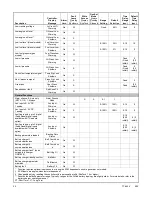
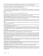
Status Event and Fault Specifications
The Factory-Defined Settings List contains all status events and faults with ranges and time delays including items that do not
have user adjustments.
Note:
The engine ECM may limit the crank cycle even if the controller is set to a longer time period.
Factory-Defined Settings List
Description
Controller
Display
Message
Alarm
Horn
Fault
Lamp
Warning
Shutdown
Write
Access
Display
SiteTech
GenSet
Mode
Always
Running
Stopped
Range
Setting
Default
Selection
Time
Delay
Range
(sec.)
Default
Time
Delay
(sec.)
Engine Functions
Critically high fuel level
(diesel-powered models only)*
Fuel Level
Critically High
On
W
0-100%
95%
0-10
5
ECM communications loss
ECM Comm Err
Shutdwn
On
S
Fixed
10
ECM diagnostics (multiple
inputs) †
ECM xxxxxx
Warning
On
W
ECM diagnostics (multiple
inputs) †
ECM xxxxxx
Shutdwn
On
S
ECM faults (address conflict)
ECM Addr Err
Shutdwn
On
S
ECM faults (model mismatch)
ECM Mismatch
Shutdwn
On
S
0-255
0
Engine over speed
Eng Speed
High Shutdwn
On
S
S
A
105-
120%
115%
Engine start aid active
Starting Aid
Notice
Engine under speed
Eng Speed Low
Shutdwn
On
S
S
A
75-95%
85%
Fuel tank leak *
Fuel Leak
Warning
On
W
Fuel tank leak *
Fuel Leak
Shutdwn
On
S
High battery voltage
Battery High
Warning
On
W
S
A
110-
135%
125%
Fixed
10
High coolant temperature
Coolnt Temp
High Warning
On
W
0-10
(0-30
inhibit)
0
(5
FAA)
(0
inhibit)
High coolant temperature
Coolnt Temp
High Shutdwn
On
S
0-10
(0-30
inhibit)
0
(0
inhibit)
High fuel level (diesel-powered
models only) *
Fuel Level High
Warning
On
W
0-100%
90%
0-10
5
Loss of fuel
Loss of Fuel
On
S
Low battery voltage
Battery Low
Warning
On
W
S
A
80-
105%
100%
Fixed
90
Low coolant level *
Coolant Lvl
Low Shutdwn
On
S
Fixed
5
Low coolant temperature
Coolant Temp
Low Warning
On
W
Fixed
16°C
(60°F)
0-10
(0-30
inhibit)
5
(0
inhibit)
* Function requires optional input sensors or is engine ECM dependent on some generator set models.
† ECM inputs are engine-manufacturer dependent.
‡ Changeable only by resetting the controller with a personality profile (SiteTech 1.4 or higher).
** Denotes the default parameter range. Typically, ranges for the NiCad battery topology are slightly wider. For more details, refer to the
battery charger operation manual.
ST- Short Term, LT- Long Term
Summary of Contents for APM402
Page 6: ...6 TP 6694 9 20 ...
Page 16: ...16 TP 6694 9 20 ...
Page 42: ...42 TP 6694 9 20 ...
Page 78: ...78 TP 6694 9 20 ...
Page 112: ...112 TP 6694 9 20 ...
Page 120: ...120 TP 6694 9 20 ...
Page 124: ...124 TP 6694 9 20 Figure 54 20 150 kW Permanent Magnet Single Phase Alternators ADV 5875AB 1 ...
Page 125: ...TP 6694 9 20 125 Figure 55 20 300 kW Permanent Magnet Alternators ADV 5875AB 2 ...
Page 128: ...128 TP 6694 9 20 ...
Page 131: ...TP 6694 9 20 131 Figure 61 Battery Charger to Controller Connections DEC 3000 Controller ...
Page 153: ...TP 6694 9 20 153 Figure 90 Controller Wiring Connections GM78246G 1 ...
Page 154: ...154 TP 6694 9 20 Figure 91 Controller Wiring Connections GM78246G 2 ...
Page 171: ......


