


Figure 20
N5252A or N5253E Configuration
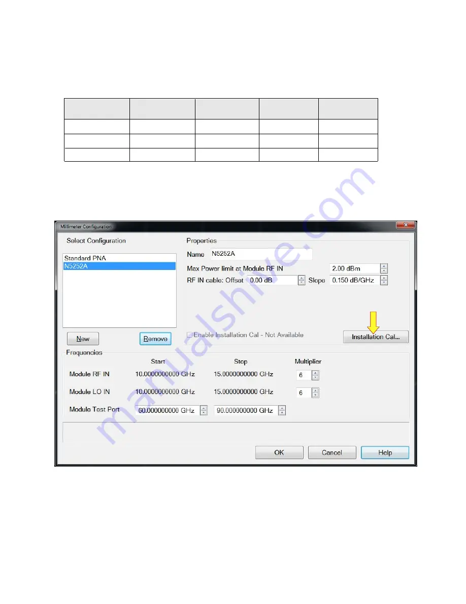
In the Network Analyzer (VNA) application, select
Setup > External Hardware > Millimeter Config
> New >
then enter the name (N5252A or N5253E) as desired. See
Table 14
and
Figure 20
below
for the settings that should be used.
N5252AW06
2
WR6.5 (D-Band)
12
Module
1
Table 14
Configuration Settings
LO Multiplier
RF Multiplier
12
110-170
Test Port (GHz)
N5253E
(or N5253E)
When your selections are made, select "OK" and restart as a "Millimeter Wave System." After
the restart is complete, return to the Select Configuration window above and select "Installation
Cal" (
Figure 20
).
1. Refer to the label on the extender for the LO Multiplier, RF Multiplier, and Test Port (GHz).
2. If using an alternative configuration, see
for
details.
6
6
75-110
6
6
60-90
6
6
50-75
N5252AW10
2
WR10 (W-Band)
N5252AW12
WR12 (E-Band)
N5252AW15
2
WR15 (V-Band)
N5252-90002 User's Guide
29
Summary of Contents for N5252A
Page 1: ...User s Guide Keysight Technologies N5252A and N5253E E Band Vector Network Analyzer Systems ...
Page 5: ...Introduction N5252 90002 User s Guide 5 ...
Page 16: ...System Setup 16 N5252 90002 User s Guide ...
Page 31: ...Figure 22 Installation Calibration Steps N5252 90002 User s Guide 31 ...
Page 33: ...Figure 23 2 Port Receiver Check Figure 24 4 Port Receiver Check N5252 90002 User s Guide 33 ...
Page 48: ...Troubleshooting Maintenance and Support 48 N5252 90002 User s Guide ...
Page 55: ...Safety and Regulatory Information N5252 90002 User s Guide 55 ...


