background image

30 Operating instructions

C 1200

Summary of Contents for Champion C 1200

Page 1: ...n Germany Postfach 1352 Telephone 49 0 2563 88 0 E mail Info Kemper Stadtlohn de Internet www kemper stadtlohn de Harvesting maize with perfect technology Operating Manual Issue B0509 English No 93 940 Champion C 1200 MOUNTED UNIVERSAL FORAGE HARVESTER ...

Page 2: ...ent 49 0 25 63 88 155 Sales Machinery 49 0 25 63 88 98 Sales Spare Parts 49 0 25 63 88 95 Customer Service 49 0 25 63 88 147 Telefon International Sales Management 49 0 25 63 88 152 Sales Machinery 49 0 25 63 88 22 88 25 88 28 Sales Spare Parts 49 0 25 63 88 22 88 25 88 28 Customer Service 49 0 25 63 88 26 88 32 88 84 Fax International Sales Management 49 0 25 63 88 155 Sales Machinery 49 0 25 63 ...

Page 3: ...asic settings of mounted forage harvester 24 0 Attachment options 25 0 Working with the forage harvester 26 0 Reversing of drum rotation in the event of blockage 30 0 Operating instructions 32 0 Grinding of blades 32 1 Inspection and adjustment of counter edge Blade wheel Smooth roller 32 2 Design and components of blade wheel 33 0 Replacement of cracker plate 34 0 Maintenance Lubrication schedule...

Page 4: ...n force of your country 14 Do not allow anyone to stay in the slewing range of the discharge chute while cutting disc is rotating 15 Front attachments may only be uncoupled on a level area 16 Relieve all pressures before disconnecting hydraulic lines Report immediately to a doctor in case of injury by hydraulic oil forced out under high pressure 17 The use of an appropriate ear protection is recom...

Page 5: ... read the Operator s Manual before handling the machine Shut off engine and remove key before performing maintenance or repair work max 1000 rpm Hydraulik Druck Hydraulic pressure of Pression Hydraulique de Hydraulische Druck max 2 1 0 bar ...

Page 6: ...ger by turning cutting rotor Keep distance Keep hands away from rotating crop dividers Put safety shields in place when grinding knives Wear safety glasses Wait until all machine components have completely stopped before touching them ...

Page 7: ... to avoid personal injury Read the users manual Avoid fluid escape under pressure Change hoses immediately A Adjust the flywheel only with safety gloves B Grind the knives with safety glasses C Close grinder sheet immediately after the flywheel has stopped turning ...

Page 8: ...ator s Manual Confirmation is required that the customer has taken possession of the machine and the Operator s Manual For this purpose send the signed document A to Kemper Document B is retained by the dealer who supplied the machine Document C is retained by the customer At the same time you will be assured that warranty is given EC Certificate of Conformity This product has been submitted to th...

Page 9: ...n facing in direction to travel Note the identification numbers of the machine on the last page of this manual This information will enable your dealer to send you quickly the correct spare parts 2 Operation in accordance with specifications The Universal Precision Forage Harvester CHAMPION from KEMPER is built solely for harvesting silage maize or other crops In conformity with the relevant regul...

Page 10: ...flywheel 1180 rpm fitted with 12 chopping blades with tungsten carbide coating and special profile for extremely efficient chopping reversible shear blade with carbide tipped edges built in blade sharpener flywheel housing fitted with replaceable wear and tear plates rasp concave for more efficient re chopping useable instead of the smooth concave Feeding unit It is composed of two feed rollers wi...

Page 11: ...8 Optional Equipment C 1200 Cutting lengths V belt pulley W Cutting knives 12 6 1 153 mm 65975 4 8 1 218 mm 65977 8 5 17 ...

Page 12: ...lve 4 1000 rpm PTO 5 Standard PTO connection 1 3 8 6 No 40496 Optional PTO connection 1 3 8 21 No 59025 Optional PTO connection 1 3 4 6 No 63254 Optional PTO connection 1 3 4 21 No 63255 PTO The main PTO shaft W 2400 is equipped wit ha slip clutch FK 96 4 M 1350 Nm The REAR and SIDE mounting versions have a clockwise free run and th e FRONT version is equipped with an anti clockwise free running c...

Page 13: ...10 Designation of assembly groups C 1200 ...

Page 14: ...rpm PTO 150 HP 21 Slip clutch K 92 4 T 1350 Nm 22 3 point hitch Cat II adjustable 23 Top link Cat II adjustable 24 Angle gear 1 with FRONT and REAR connection 25 Angle gear 2 in swiveldrive 26 3 point hitch frame 27 Hitch not for heavy weights 28 PTO shaft between the gear cases 29 V belt power with free running clutch 30 Angle drive on flywheel cutting disc 31 Changeable V belt disc for chop leng...

Page 15: ...12 Champion harvesting technology C 1200 ...

Page 16: ...ugh narrow spacing Methods of cultivation Alternative methods of corn cultivation are not only more and more discussed but also already practiced by institutions and farmers higher yields are achieved by increasing the number of plants per surface unit The new technique allows the existing seed drill to be used but has only became possible with the introduction of the row independent Champion cutt...

Page 17: ...19 Technical instructions C 1200 ...

Page 18: ...by the tractor driver c The permissible total weight of the trailer is not superior to the permissible total weight of the tractor x 1 25 but at most 5 tons Overload protection in the spur gear drive of the precompression rollers Fig 30 The friction clutch of the PTO drive shaft protects the drive system and flywheel against overload Any overload in the feed mechanism will activate the pin type sa...

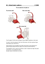
Page 19: ...19 Technical instructions C 1200 ...

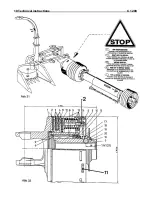
Page 20: ...ch of the main PTO drive shaft Fig 32 Overload protection The friction clutch in the main PTO drive shaft protects the whole machine from overload It is therefore INDISPENDABLE to check the function of this clutch periodically Torque setting The clutch torque is set to 1350 Nm To maintain this setting it is essential to perform the maintenance jobs described in the following two sections Warranty ...

Page 21: ...ng so that it is not damaged or twisted when the ejection chute is moved Do not tighten the cable but ensure that there is ample play The ejection chute can be folded down e g in the event of a blockage To do this loosen the two brackets The clamping force of the brackets can be adjusted by means of the eyebolts When placing the ejection chute onto the flange surfaces ensure that they are clean Th...

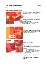
Page 22: ...r to the front of the tractor turn the input bevel gear transmission see instructions If the machine is to be operated to the side of the tractor ensure that there is sufficient space between the rear wheel of the tractor and the divider tip The headstock can be moved on the frame in order to adjust the forage harvester to the tractor in an optimised position See also section Attachment to tractor...

Page 23: ... transmissions Remove the two M8 screws and mount the protective cap on the opposite side Remove the four M10 screws to the left and right of the transmission Swivel protective plate Before the transmission can be turned by 180 replace the bleeder screw with a seal screw To do this proceed as follows Turn the 90 transmission The oil remains in the transmission Replace the oil filler screw with ble...

Page 24: ...ng key and stop for front and rear mounting Adjust the stops so that the drives are aligned and the securing key is properly inserted Caution It is forbidden to stand in the swivelling range of the machine Before swivelling the machine ensure that the machine is attached in a horizontal position Otherwise the machine might swivel due to its own weight when the securing key is removed Special care ...

Page 25: ...ed by means of the hydraulic system and the jockey wheel if attached Make the following adjustments when the machines are standing on level and even ground Adjust the forage harvester to its working height and secure it in that position by means of the tractor hydraulics The chopping unit is now in its basic position and does not need to be readjusted The header is lifted and lowered with the trac...

Page 26: ...the intake at full motor speed The intake can only be switched on and off i e for reversing to remove blockages at full speed even in fast sequence as long as the blade rotors remain at nearly the same speed due to the freewheel mechanism Cutting lengths The chopping lengths can be adjusted quickly by exchanging the V belt pulleys 1 2 The cutting length can also be adjusted more finely by removing...

Page 27: ...ulley 1 153 no 65975 V belt pulley 2 218 no 65977 Lodged crop worm The header can be equipped with a lodged crop worm driven by the intake drum No 65960 Crop divider complete Cutting lengths V belt pulley Chopping blade 12 6 1 180 2 210 5 10 1 210 2 180 7 5 15 Fig 40 Cutting lengths V belt pulley Chopping blade 12 6 1 153 2 218 4 8 1 218 2 153 8 5 17 Fig 40A ...

Page 28: ...ersing Switch off all drives shut down the engine and let all parts come to a standstill To reverse the header us a lever Turn the lever so that the intake drum rotates against its intake direction Disengage the drive shaft from the tractor Order no 85393 ...

Page 29: ...30 Operating instructions C 1200 ...

Page 30: ...get a enough food flow into the chopper During extremely difficult conditions like wet laid crops with a lot of weed on a sandy soil the operator should have some practice as regards selection of the right forward speed steering the machine and use of the stem lifters Down crops Depending on the operation conditions it might be commendable to install fixed stalk lifter tips for down crops as shown...

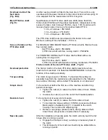
Page 31: ...nut from the sharpening device Turn the manual handle in the direction of the chopping wheel until the blades touch the sharpening device Complete another 1 2 rotation of the handle thus pressing the grinding disk against the blades Important Ensure that the grinding disk rotates with the blades during grinding Adjust the speed The faster the blades rotate the higher the abrasive effect of the gri...

Page 32: ...s Realign chopping wheel After the chopping wheel has been re sharpened it must be realigned to the counter edge Open the housing cover of the chopping wheel Remove the anti rotation element lock spring from its seat The nut is now accessible Place the included 16 mm mounting bar onto the square head of the nut ...

Page 33: ...n which the lock spring can be engaged in the groove of the nut The blade wheel may not touch the counter edge If necessary repeat the above adjusting procedure check the counter edge and set the blade wheel back by one groove The blades can be adjusted by means of the oblong holes so that a uniform distance to the counter edge can be achieved Caution observe correct tightening torques ...

Page 34: ...age etc See also chapter Changing of counter edge See chapter Pre compression channel Load shovels Optimised chop transport can only be achieved with undamaged and correctly mounted load shovels They can be turned up to four times INCORRECT CORRECT Counter edge Counter edge Chopping blade Chopping blade ...

Page 35: ... If necessary adjust the output speed of the tractor until sparks are produced at the grinding disk Caution The faster the blades rotate the higher the abrasive effect of the grinding disk To adjust the grinding effect simply adjust the blade wheel speed too hard reduce speed too soft increase speed If the speed is too high the grinding disk surface becomes smooth and shiny Its coarseness can be r...

Page 36: ...s Replacement and adjustment of counter edge To adjust and replace the counter edge open the housing of the pre compression rollers In order to be able to increase the opening angle of the pre compression channel remove the jockey wheel First release the belt and then remove from the cutting rotor The tension spring can be released by moving the lever To release the lever loosen the size 12 hexago...

Page 37: ...edge Blade rotor smooth roller C1200 Remove the tension spring from the top belt pulley Remove the 12x35mm screw Remove the top pulley together with the belt Remove the lower pulley and belt or lift the belt from the pulley Disconnect the two con rods ...

Page 38: ...ve the forage harvester from the front or rear position to the side First disconnect the drive shaft from the variable speed transmission Opening of drum housing To open the drum housing by swivelling it from the pre compression roller housing first install the top belt and pulley Remove the tension spring from the drum drive unit When removing the tension spring hold it with an assembly rod and t...

Page 39: ...ler C1200 Remove the pressure roller by removing the circlip and pulling the reversing lever with roller Remove the large drum belt The drum housing can now be opened Secure the hosing against inadvertent closing When closing the housing ensure that the stop is properly engaged ...

Page 40: ...l is balanced at the factory Therefore never mount a set of wheels that are not supplied together To ensure balance the blades shear bars and transport shovels must be replaced in pairs at positions opposite each other The maximum permissible weight difference is 20 g ...

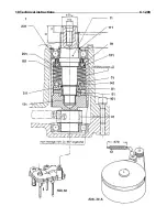
Page 41: ... 60727 Nut 1 15 62294 Inner ring IR 65x75x28 1 16 49041 Wheel seal ring 75x95x10 BA 1 17 46357 Lubrication nipple H1 M6x1 D71412 3 16 62988 Lubrication nipple pipe 1 19 65140 Balancing weights X 20 68050 Chopping blades 12 21 37103 Disk spring 36 22 55205 Securing screw V Ripp 10x25 36 special Important Torque for these screws 130 Nm 23 35804 Disk spring 90x46x2 5 6 24 35626 Back up washer SS 45x5...

Page 42: ...32 2 Blade rotor C1200 Installation position ...

Page 43: ...acker plate can be adjusted by placing washers between the cracker plate and the housing The smaller the gap between the blade wheel and the cracker plate the smaller the corns are chopped Remove the two M 10 x 70 mounting screws Remove the cracker plate Re mount in reverse order The outer cracker plate panel 3 can be equipped with a smooth plate 1 or a cracker plate 2 When changing plates ensure ...

Page 44: ... mm from eyelet to eyelet The preload of the pre compression rollers can be adjusted by means of the size 10 screw The dimensions shown here are recommended values In certain cases the setting might deviate from these Wear at intake drums The front intake drums are equipped with drivers When these are worn crop flow might be hampered The drivers can be welded on if necessary Ensure that the driver...

Page 45: ...35 Greasing chart C 1200 ...

Page 46: ...e Periodically grease all hinge points P Oil level check plug Grease semi fluid Aviaticum XRF Greasing chart 1 Feed roller lower bearing 2 Feed roller lower bearing 3 Precompression roller lower bearing 4 Pivot top bearing 5 Pivot lower bearing 6 Free wheel mechanism 7 Intake drum lower bearing 8 Intake drum top bearing 9 Flywheel cutting disc front bearing grease nipple on gearbox 10 Flywheel cut...

Page 47: ...35 Greasing chart C 1200 ...

Page 48: ...35 Greasing chart C 1200 ...

Page 49: ... 2500 1850 3150 2350 2900 2150 3700 2750 M 36 1150 850 1450 1075 2250 1650 2850 2100 3200 2350 4050 3000 3750 2750 4750 3500 The tightening torques are indicated in the table are approximately values and do NOT apply wherever other tightening torques are quoted in this manual Bolts and nuts have to be checked periodically for tightness The shear bolts are designed in such a way that they break if ...

Page 50: ...disc Check the shear bar of the cutting disc Reverse the shear bar if necessary Check the pivot and the angle drive Lubricate the implement in accordance with the greasing chart Annual maintenance Clean the machine and treat it with an anticorrosive agent Change the oil in the gearboxes observe the oil quantity laid down by the manufacturer Check all components for wear Order genuine spare parts i...

Page 51: ...38 Maintenance and inspection C 1200 ...

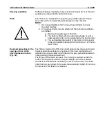
Page 52: ...er is a maxi output machine which should be kept in good condition at all times Because of most of the power is required by the chopping unit the position of the shear bar should be checked daily Flywheel cutting disc Safe operation of the flywheel cutting disc can be only ensured if the contact surface of the knives is clean and the attaching bolts are pulled up to the correct torque Operate the ...

Page 53: ...38 Maintenance and inspection C 1200 ...

Page 54: ... 8 Release tension nut 10 and carefully swing round the machine The mowing attachment intake drum can also be swung round separately To this end slacken spring 12 and remove power band 11 from roller 13 When reassembling the unit make certain that the power band is at the correct tension Tension will be correct when spring 12 is compressed to 270 mm measured between both eyelets Cleaners fig 57 Th...

Page 55: ...40 Electric circuit diagram C 1200 ...

Page 56: ...y to the top and the other to the bottom b Tines should pass as close as possible to strap 4 or 5 c If necessary build up both tine points by welding Maize stems are folded to the front before being cut long uneven stubble a Leaves or stems accumulated around the small divider points b Cleaners under knives broken away a Clean divider points b Renew cleaners Intake drum stops rotating a Overload b...

Page 57: ... see chapter 34 Insufficient spring tension Tension spring as shown in chapter 34 Main drive belt slipping a Defective spring b Too low a belt tension a Renew the spring b Retension the belt Observe the measurement 83 mm Sharpening device vibrating a Excessive speed at the cutting disc b Grinding stone too close to the knives a Reduce the speed of the cutting disc b Move grinding stone away from k...

Page 58: ...ng device Meule d aiguisage 1 5 61098 2 fach Gegenschneide Counter blade Contre couteau 1 6 50076 Senkschraube 12x45 Countersunk screw Vis special pour contre couteau 3 7 66333 Abstreifer konisch 36 65x20x340 Cleaner of the reaper Decrotter pour rouleau lise 1 8 58283 Sägemesser Cutting blade Segment de scie 6 9 05639 Schraube 8x16 D 933 V Screw Vis 24 10 67156 Räumer 158 innen Cleaner Debourreur ...

Page 59: ...atement 1 17 49779 Senkschraube 12x30 Countersunk screw Vis special pour contr couteaux 8 18 63331 Verbundkeilriemen 3 HB x 3155 Joined V belt Triple 1 19 63332 Verbundkeilriemen 3 HB x 1990 Joined V belt Triple 1 20 63330 Keilriemen 22 x 2340 V belt Courroie 1 21 63333 Keilriemen 22 x 1200 gezahnt V belt Courroie 1 22 66318 Wurfplatte Impeller plate Piece de ventilation 12 23 55040 Sich Schraube ...

Reviews: