19 Technical instructions
C 1200
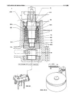
Overload clutch of the
feed drum
(Fig. 30 A)
Another overload clutch is fitted to the feed drum. This clutch is only
operative with the power band set to the correct tension when spring 12
is so adjusted that the measurement 270 mm is given.
Main PTO drive shaft
(Fig 31)
Specifications of the PTO drive shaft: size 2400, tubes S4LH/S5,
friction clutch FK 96/4 with freewheel mechanism, independent of the
sense of rotation, clutch torque 1350 Nm, clevis 1 3/8, 6 splines, with
lock pin (tractor side). Clevis size for another tractor PTO’
s:
1 3/8 – 21 splines = PN 59025
1 3/4 – 6 splines = PN 63254
1 3/4 – 20 splines = PN 63255
The PTO drive shaft has to be adapted to the tractor to be used.
Minimum overlap of the shaft tubes = 150 mm.
Sense of rotation of the
PTO drive shaft
For REAR and SIDE MOUNTING the PTO drive shaft is fitted with a cw
free running clutch:
Cpl. PTO drive shaft = PN 68950
½ PTO drive shaft with free running clutch = PN 69254
For FRONT MOUNTING the PTO drive shaft is fitted with a ccw
rotating free running clutch:
Cpl. PTO drive shaft = 68951
½ PTO drive shaft with freewheel running mechanism: PN 69255
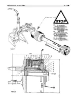
Friction clutch of the main PTO drive shaft – Fig 32
Overload protection
The friction clutch in the main PTO drive shaft protects the whole
machine from overload. It is therefore INDISPENDABLE to check the
function of this clutch periodically.
Torque setting
The clutch torque is set to 1350 Nm. To maintain this setting it is
essential to perform the maintenance jobs described in the following
two sections. Warranty will be voided if this advise is not observed.
Simple check
To be carried out before the first use of the machine and after long
periods of storage:
•
Tighten the nuts (2) to relieve the friction discs of load. Rotate
the clutch.
•
Unscrew the nuts (2) up to the end of the threaded position.
Detailed check
To be carried out at every start of season:
•
Tighten the nuts (2) to relieve the friction discs of load.
•
To maintain the torque setting (=1350 Nm) proceed as follows:
Mark position of adjusting ring 11 in relation to the clutch
housing. Then remove the adjusting ring.
•
Remove cup springs, pressure discs, driving discs and hub.
Clean these components or replace them if necessary.
New slip pads
After the installation of new slip pads, the clutch will only reach the full
torque after a running-in period.
•
Engage the Champion slowly, avoid any unnecessary load of
the clutch
•
The full capacity of the machine should only be utilized after a
running-in period.
Summary of Contents for Champion C 1200
Page 13: ...10 Designation of assembly groups C 1200 ...
Page 15: ...12 Champion harvesting technology C 1200 ...
Page 17: ...19 Technical instructions C 1200 ...
Page 19: ...19 Technical instructions C 1200 ...
Page 29: ...30 Operating instructions C 1200 ...
Page 42: ...32 2 Blade rotor C1200 Installation position ...
Page 45: ...35 Greasing chart C 1200 ...
Page 47: ...35 Greasing chart C 1200 ...
Page 48: ...35 Greasing chart C 1200 ...
Page 51: ...38 Maintenance and inspection C 1200 ...
Page 53: ...38 Maintenance and inspection C 1200 ...


