


36
Data transfer
ServoOne User Manual SERCOS II and III
ID no.: 1108.26B.3-00 Date: 04/2020
Data transfer
NOTE:
For the operation of a drive controller via SERCOS III, the drive control word
(S-0-0134.0.0) must be mapped to the MDT and the drive status word
(S-0-0135.0.0) to the AT; unlike for SERCOS II these words are no longer a
fixed part of the MDT or AT.
7.3.2
Drive control word S-0-0134.0.0
The drive control word contains all important control information for the drive and must
be mapped to the cyclic part of the MDT.
Bit no.
Description
15
Drive on / off
x
Drive OFF: On the change from 1
0 the drive is shut down in the best manner
possible (corresponding to the setting in
P 2219
) with, if necessary, the subse-
quent shutdown of the torque at standstill; the power stage can remain activated
(only possible if bit 14 = 1 and there is a corresponding setting in
P 2219
).
x
1: Drive on
14
Drive enable
x
0: No enable. On the change from 1
0 the torque is shut down without a
delay and the power stage inhibited (independent of bit 15 and 13).
x
1: Drive enable
13
Drive stop (can be used to shut down the drive without taking into
account the control function currently active)
x
0: Drive stop: The drive no longer follows the reference values. On the change
from 1
0 the drive stops as per the setting in
P 2221
and taking into account
the acceleration active last (by default the acceleration parameter
P 2242
applies) and remains under control (only possible if bit 14 and 15 = 1 and with a
suitable setting in
P 2221
).
x
1: Drive start: On the change from 0
1 the original function is continued. If
the controller has not updated the position, reference value steps and therefore
shutdown due to tracking errors may occur.
12
Reserved
11
Toggle bit: new reference values
The bit is valid in communication phase 3 + 4, changes synchronously with the "Pro-
ducer cycle time" (S-0-1050.0.10) and indicates the availability of the new reference
values for the slave.
Table 7.1
Drive control word S-0-0134
Bit no.
Description
10 – 8
Required operation mode
x
000: Main operation mode (definition in S-0-0032.0.0)
x
001: Secondary operation mode 1 (definition in S-0-0033.0.0)
x
010: Secondary operation mode 2 (definition in S-0-0034.0.0)
x
011: Secondary operation mode 3 (definition in S-0-0035.0.0)
x
100: Secondary operation mode 4 (not supported)
x
101: Secondary operation mode 5 (not supported)
x
110: Secondary operation mode 6 (not supported)
x
111: Secondary operation mode 7 (not supported)
7 – 0
Reserved
Table 7.1
Drive control word S-0-0134
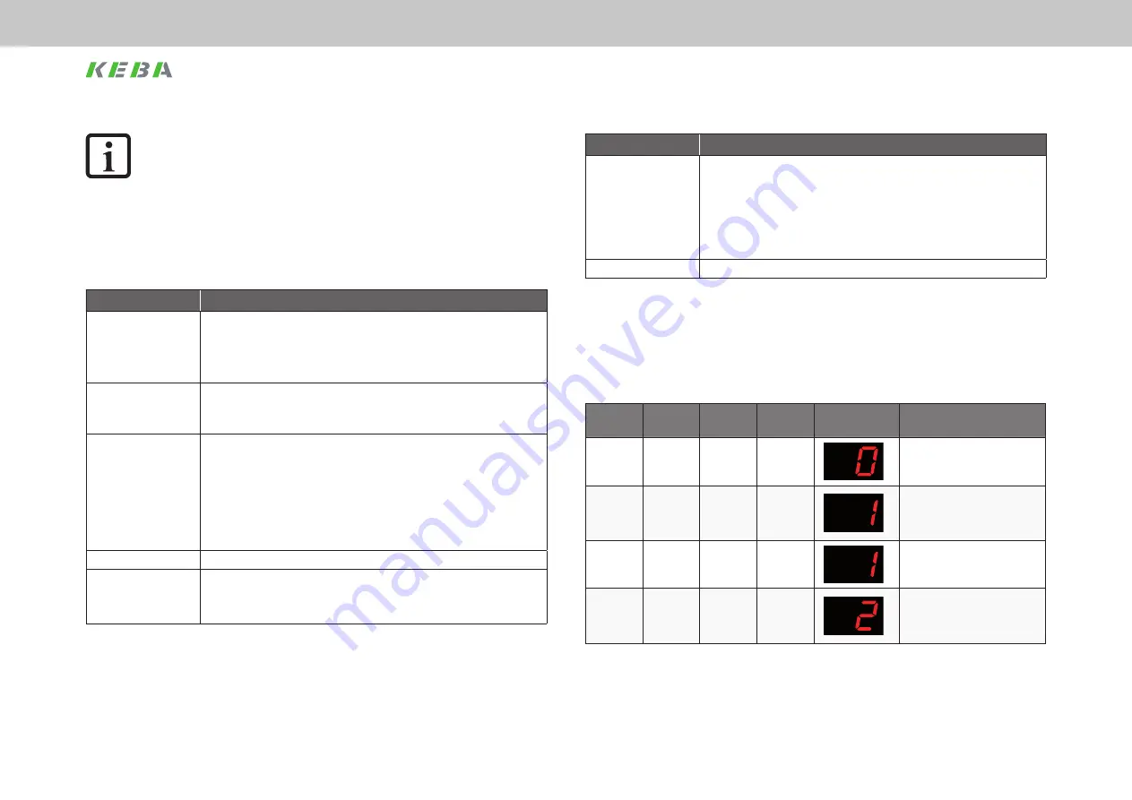
7.3.3
Description of the bits 13-15
The system state of the drive is indicated on the display on the front of the device.
One of eight possible system states is indicated using bits 15, 14, 13 and 3 of the
SERCOS status word as per the following table. The drive state machine (SERCOS) is
described in the next chapter.
Bit 15
Bit 14
Bit 13
Bit 3
Display
System state designation
0
0
0
0
START
Drive in the initialisation phase
0
1
0
0
Not ready to switch on
Power stage not powered, no DC
link voltage,
STO input required
0
1
0
0
Not ready to switch on
Power stage not powered, no DC
link voltage
1
0
0
0
Start inhibit
Power stage not powered, not
enabled, no DC link voltage, STO
input required
Table 7.2
Representation on bits 3, 13, 14 and 15 of the system state
Summary of Contents for ServoOne Series
Page 10: ...10 ServoOne User Manual SERCOS II and III ID no 1108 26B 3 00 Date 04 2020...
Page 54: ...54 ServoOne User Manual SERCOS II and III ID no 1108 26B 3 00 Date 04 2020...
Page 78: ...78 ServoOne User Manual SERCOS II and III ID no 1108 26B 3 00 Date 04 2020...
Page 84: ...84 ServoOne User Manual SERCOS II and III ID no 1108 26B 3 00 Date 04 2020...
Page 85: ...85 ServoOne User Manual SERCOS II and III ID no 1108 26B 3 00 Date 04 2020...


