background image

6   Using the device

5.

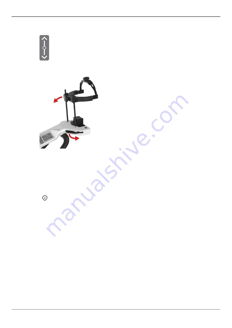
Adjust the device's height to approximately match the patient's height by sliding a finger on the
carriage up/down slider.

6.

Open the head support locking lever on the lower shelf, push the head support towards the mirror
and lock it leaning forward.

7.

Tell the patient to remove their glasses, hearing aids, removable dentures, jewellery, hair clips and
all other things that can cause artifacts to the image.

8.

Protect the patient from radiation according to the local regulations, for example with a lead
apron and a thyroid shield.

9.

Guide the patient to the device and instruct to stand as straight and as tall as possible.

10.

Ask the patient to grab the patient handles, place their chin on the Chin Rest and to press their lip
against the Lip Support.

NOTICE! 

 If the patient has wide shoulders that could collide with the rotating unit, ask the

patient to cross their arms when holding the handles in order to contract the soulders.

11.

Ask the patient to take a step forward to straighten their spine.

64

ORTHOPANTOMOGRAPH

 OP 3D

Summary of Contents for ORTHOPANTOMOGRAPH OP 3D

Page 1: ...Dental Excellence OP 3D ORTHOPANTOMOGRAPH OP 3D User Manual 212972 rev 30 0 805 4913 ENGLISH...

Page 2: ......

Page 3: ...Cephalometric lights 13 3 2 4 3D lights 13 3 3 Accessories 14 3 4 Other detachable parts 15 3 5 Emergency stop switch 16 3 6 Device connectors 17 4 User interfaces 18 4 1 Graphical User Interface GUI...

Page 4: ...2 2 Preparation for calibration 71 7 2 3 Calibration procedure 73 7 3 Quality control 77 7 3 1 PAN QC 77 7 3 2 CEPH QC 80 7 3 3 3D QC 82 7 4 Annual maintenance 84 8 Troubleshooting 85 9 Technical dat...

Page 5: ...prior written permission of PaloDEx Group Oy The original language of this manual is English PaloDEx Group Oy reserves the right to make changes in specification and features shown herein or disconti...

Page 6: ...erior Anterior PA projection Carpus view 3D CBCT Imaging FOV Volume Height x Diameter 5 x 5 6 x 8 6 x 9 8 x 8 9 x 11 9 x 14 Resolution LDT Low Dose Technology Standard High Endo 5 x 5 only Scout image...

Page 7: ...operated by dentist and other qualified professionals 2 3 Intended user profile Only for professionally qualified dental medical personnel Typical user is a dental assistant with specific training fo...

Page 8: ...s injury CAUTION Indicates a hazardous situation which if not avoided could result in minor or moderate injury NOTICE Highlights suggestions which will result in enhanced installation reliability or o...

Page 9: ...y images of pediatric patients and where feasible adjust the radiation field size Where it is likely that evaluation of soft tissues will be required as part of the patient s radiological assessment t...

Page 10: ...hese requirements must not be connected to the device as they may pose a threat to the operational safety Electronic equipment workstation network connecting devices etc that do not fulfill medical sa...

Page 11: ...0 Power switch Back of the device 11 Emergency stop switch 12 Exposure switch 13 Mirror 14 Lower shelf tray 15 Patient handles 16 Head support 17 Head support locking lever 18 Chin rest CEPHALOMETRIC...

Page 12: ...A Tilt light PAN imaging B Midsagittal light C Horizontal light top of FOV FH light D Horizontal light bottom of FOV E Cephalometric FH light CEPH devices 3 2 2 Panoramic lights B C A A Tilt light B...

Page 13: ...light NOTICE Lateral programs only 3 2 4 3D lights B C D B Midsagittal light C Horizontal light top of FOV D Horizontal light bottom of FOV NOTICE The position of the top of FOV light is automatically...

Page 14: ...older optional Disposable covers for patient positioning accessories Disposable covers for Bite Block Disposable covers for Lip Support Disposable cover sheets for Chin Rest and Head Support Disposabl...

Page 15: ...calibration phantom CEPH calibration rod CEPH only 3D QUALITY CONTROL TOOLS 3D QC phantom 3D QC phantom holder 2D QUALITY CONTROL TOOLS OPTIONAL 2D QC test phantom Copper filter 0 8 mm 1 8 mm PAN QC...

Page 16: ...An interrupted imaging process cannot be resumed A new image needs to be taken To release the emergency stop switch rotate it clockwise NOTICE Make sure that the emergency stop switch is not pressed...

Page 17: ...ctor optional 5 External warning light connector optional 6 Main fuses F1 F2 10 A fuses pre installed 7 External warning light fuse F3 2 A fuse pre installed 8 Control interface NOTICE All cables exce...

Page 18: ...AP estimation Shows the estimated duration of X ray radiation and the radiation dose with the selected imaging program and parameters The actual imaging parameters and DAP are shown after imaging 7 Sa...

Page 19: ...eset Select the patient size preset according to the patient to adjust the kV and mA to preset levels NOTICE Patient size presets can be adjusted from device settings STATUS MESSAGE BAR Message bar Th...

Page 20: ...ed Press the segments to select green and deselect gray them Panoramic imaging programs Indicates which imaging program is selected Press the imaging program icons to change the active imaging program...

Page 21: ...d in you can click and drag to scroll the image Brightness slider You can adjust the brightness of the shown preview image using the brightness slider Contrast slider You can adjust the contrast of th...

Page 22: ...t cephalometric view The cephalometric view shows which parts of the skull are imaged with the selected imaging program In lateral imaging the image field width can be manually adjusted by dragging th...

Page 23: ...ection Pediatric lateral projection PA projection Carpus view NOTICE The carpus view program requires an optional carpus holder A sample image for the selected imaging program is shown on the bottom o...

Page 24: ...med in you can click and drag to scroll the image Brightness slider You can adjust the brightness of the shown preview image using the brightness slider Contrast slider You can adjust the contrast of...

Page 25: ...n it 3 or 4 Both jaws and all teeth in them 3 and 4 TMJ 5 or 6 Both TMJ s 5 and 6 Whole dentition 3 4 5 and 6 NOTICE Both TMJs are selectable only if 9 x 14 FOV size is available You can select all pa...

Page 26: ...ary method for FOV size selection NOTICE The list of available FOV sizes depend on the device configuration and country specification Image resolution Indicates the currently selected resolution Press...

Page 27: ...activate it When the Scout image program is active the FOV coverage illustration turns green 4 1 4 2 SMARTVIEW 2 0 scout image view The green rectangle on the scout image represents the imaged FOV You...

Page 28: ...he FOV position It s recommended to adjust the FOV location so that the ROI is in the middle of the volume Brightness slider You can adjust the brightness of the shown Scout image using the brightness...

Page 29: ...and H F Head Foot Preview projection Indicates which preview projection is selected 3D preview image is shown as a slice preview left and a rendered volume right on the GUI Press the preview projectio...

Page 30: ...ider You can adjust the brightness of the shown preview image using the brightness slider NOTICE Adjustment is not saved to the image Contrast slider You can adjust the contrast of the shown preview i...

Page 31: ...selection icon to open a list of available image resolutions LDT resolution Standard resolution High resolution Press on the listed resolution icon to activate it Scout image program Indicates if the...

Page 32: ...to the scout image by sliding the adjustment icons left or right on the scale The left slider adjusts the FOV position in Posterior P Anterior A direction and the right slider in Left L Right R direc...

Page 33: ...which direction the image is shown A P Anterior Posterior L R Left Right and H F Head Foot Preview projection Indicates which preview projection is selected 3D preview image is shown as a slice previ...

Page 34: ...e shown preview image using the brightness slider NOTICE Adjustment is not saved to the image Contrast slider You can adjust the contrast of the shown preview image using the contrast slider NOTICE Ad...

Page 35: ...e quality control images 2 CALIBRATIONS Shows a list of user performable device calibrations their completion status and last completion date The calibrations are carried out through this menu See cha...

Page 36: ...y Enable or disable automatic Scout image activation when a 3D imaging modality is selected It is recommended to have the Scout image taking enabled NOTICE If the selection is set to disabled a Scout...

Page 37: ...lues for medium size patient preset Other patient size selections are changed relatively to the adjustment made Adjustments made to the 3D imaging program with standard resolution are applied relative...

Page 38: ...efault gateway IP address allocation MAC address NTP server 5 SERVICE MODE NOTICE This menu is intended for authorized service personnel only This menu is used to unlock Installation and Service speci...

Page 39: ...sing the HOME button also wakes the device from Power save mode 3 Test mode button Disables radiation production of the device You can also use the GUI to activate the Test mode 4 Patient positioning...

Page 40: ...icator light located on the top of the carriage illuminates according the device status YELLOW Device is generating X rays BLUE Device is in error state or pending user action Check the GUI for detail...

Page 41: ...red Press the segments on the dental chart to deselect and select them Pediatric Panoramic imaging program The Pediatric Panoramic imaging program provides a general view of the dental and facial anat...

Page 42: ...le scan Press the segments on the dental chart to deselect and select them TMJ lateral projection Lateral TMJ program provides a lateral view of the patient s left and right temporomandibular joints Y...

Page 43: ...ear rods with the smallest image width selection The exposure time depends on the width of the selected image field Cephalometric pediatric lateral projection The pediatric lateral projection is a lat...

Page 44: ...n PA projections the patient faces away from the tubehead to keep the radiation dose to patient s eyes in minimal level PA projection uses a full height image field Carpus view optional The carpus vie...

Page 45: ...corresponds to a cylindrical volume with diameter of 5 cm and height of 5 cm NOTICE Fine adjustment of the FOV location and FOV height can be done using the scout images The location of the FOV is det...

Page 46: ...on FOV 6 x 9 Optimized for multiple implant placement using surgical guides imaging the whole dental arc of one jaw 3rd molar visualization pathology bilateral analysis and periodontal cases Available...

Page 47: ...mage quality and radiation dose to the patient For example high resolution will produce more details than standard resolution but the radiation dose is also higher The unit offers a LDT Low Dose Techn...

Page 48: ...cast program The dental cast program is initially taken with FOV 9 x 11 The height of the FOV can be adjusted after scout image Available resolutions LDT resolution Standard resolution High resolutio...

Page 49: ...6 Using the device 6 Using the device 6 1 General imaging workflow ORTHOPANTOMOGRAPH OP 3D 49...

Page 50: ...power save mode the device cooling fan is not active but the patient positioning panel lights are lit The device wakes up from the power save mode when connection to it is established or when the HOM...

Page 51: ...ercise special care when imaging patients outside the typical adult size range especially smaller pediatric patients When imaging pediatric patients follow the ALARA As Low As Reasonably Achievable pr...

Page 52: ...ients seated for easier positioning 1 Press HOME button on the patient positioning panel The device moves to HOME Patient In position NOTICE Make sure that the device is set up correctly for the inten...

Page 53: ...hin Rest Lip Support Chin Rest NOTICE The Chin Rest has magnets to keep it in place NOTICE The Chin Rest needs to be attached to the device in the correct orientation for the selected imaging program...

Page 54: ...he handles in order to contract the shoulders 11 Ask the patient to take a step forward to straighten their spine 12 Fine adjust the device s height and adjust patient s head position orientation usin...

Page 55: ...the horizontal light The FH light indicates the center of the field You can take a TMJ image with the patient s mouth closed or open 13 Check that the patient s head is straight and not rotated and t...

Page 56: ...the temple supports against the patients head and close the locking lever to lock the head support in place 16 Ask the patient to close their lips and press their tongue against the palate if possible...

Page 57: ...set up correctly for the required examination 2 The device goes to ready state and the status indicator light turns green NOTICE If the status indicator light does not turn green look for more informa...

Page 58: ...tion according to the local regulations for example with a lead apron and a thyroid shield 9 Guide the patient to the device and instruct to stand as straight and as tall as possible 10 Turn the ear r...

Page 59: ...A PROJECTION The patient s Frankfort Horizontal plane should be horizontal NOTICE The horizontal light is not lit for PA projections PA REVERSE TOWNE PROJECTION Turn the patient s head downwards until...

Page 60: ...Turn the nasion support down and slide it against the patient s nasion when taking Lateral projections NOTICE If the patient has wide shoulders that could collide with the rotating unit ask the patien...

Page 61: ...Patient In position NOTICE Ensure that the device has been set up correctly for the required examination 2 The device goes to ready state and the status indicator light turns green NOTICE If the statu...

Page 62: ...their palm against the carpus holder with their fingers spread apart and wrist straightened The palm of the hand should face the sensor NOTICE Only the center area of the carpus holder is exposed Ensu...

Page 63: ...t turns green NOTICE If the status indicator light does not turn green look for more information on the GUI 3 Select the patient positioning accessory according to the image to be taken attach it to t...

Page 64: ...age 8 Protect the patient from radiation according to the local regulations for example with a lead apron and a thyroid shield 9 Guide the patient to the device and instruct to stand as straight and a...

Page 65: ...occlusal plane should be horizontal and the ROI is between the top and bottom FOV lights NOTICE You may place a cotton roll or similar between the patient s front teeth to separate the jaws 13 Check...

Page 66: ...6 Using the device 16 Lower the head support strap behind patient s head and tighten it to minimize the patient movement 66 ORTHOPANTOMOGRAPH OP 3D...

Page 67: ...nd locks the device in place to prevent unwanted movement NOTICE This is an optional step but decreases the imaging process time and the time that the patient must stay still NOTICE The device stays i...

Page 68: ...ng the exposure button to take another scout image Scout images produce only a small radiation dose so taking additional scout images won t produce excessive radiation dose to the patient 9 GUI Approv...

Page 69: ...the GUI 1 Attach Chin rest to the lower shelf of the device 2 Attach the Dental cast holder over the Chin rest 3 Place the dental cast on the holder as shown on the GUI 4 Protect yourself from radiat...

Page 70: ...protective equipment during the decontamination process Autoclave Lip Supports and Bite Blocks may be autoclaved in 121 C 250 F temperature for max 3 minutes Other parts are not autoclavable NOTICE A...

Page 71: ...the change the frequency of the recalibration reminders contact service for assistance DEVICE CALIBRATION BASIC GUIDELINE 1 The device must be recalibrated completely at least once a year by a service...

Page 72: ...performed or failed Recalibration is required Calibration performed successfully 4 Select a calibration program and follow the instructions on the GUI NOTICE Performed calibrations are indicated with...

Page 73: ...this calibration NOTICE This calibration produces X rays Protect yourself from radiation 1 Select 3D pixel calibration from the Calibrations menu 2 Protect yourself from radiation 3 Press and hold th...

Page 74: ...to take the calibration image 4 When the exposure warning stops and the program end tone is played the program is complete 5 The calibration image appears on the GUI 6 Acknowledge the calibration resu...

Page 75: ...ation 6x9 FOV 3D geometry calibration 8x8 FOV 3D geometry calibration 9x11 FOV 3D geometry calibration 9x14 FOV Geometry Calibration Phantom is required when performing these calibrations 1 Attach the...

Page 76: ...calibration image appears on the GUI 6 Acknowledge the calibration result by pressing the OK button 7 2 3 5 CEPH pixel calibration This program calibrates the sensor for Cephalometric imaging No calib...

Page 77: ...least once a month and always after calibration NOTICE The device will automatically remind of retaking the QC images If you want the change the frequency of the reminders contact your service for as...

Page 78: ...t of the radiation window on the PAN 3D tubehead The filter attaches in place with magnets 5 Protect yourself from radiation 6 Press and hold the exposure button down to take the QC image 7 The QC ima...

Page 79: ...reference image taken during the installation or the latest service Doing this helps you ensure that the image quality has remained constant NOTICE The line pair resolution depends also on the other f...

Page 80: ...med where local regulations require it 1 GUI Go to device settings 2 GUI Select CEPH QC program from the Quality control menu 3 Turn the CEPH head support to PA position 4 Turn the nasion support asid...

Page 81: ...ter if 0 8 mm copper filter was used d Low contrast holes must be visible 4 holes if copper filter was not used 2 holes if 0 8 mm copper filter was used NOTICE You should also compare the new QC image...

Page 82: ...2 GUI Select 3D QC program from the Quality control menu 3 Attach the 3D QC phantom holder and the 3D QC phantom to the device 4 Protect yourself from radiation 5 Press and hold the exposure button do...

Page 83: ...CE You should also compare the new QC image to the reference image taken during the installation or the latest service Doing this helps you ensure that the image quality has remained constant 9 If the...

Page 84: ...l covers and mechanical parts are correctly secured and have not come loose Check that any vents in the covers are not blocked with dust and that no dust has accumulated inside the device Check the fu...

Page 85: ...the local area network Check the device configuration 1 Power the device on 2 Check the Ethernet cable connections on the workstation and the device 3 Restart the device and the workstation Device sho...

Page 86: ...ible cause Solution GUI shows a message Detach carpus holder even though the carpus holder is not attached Issue in CEPH head support calibration Recalibrate the CEPH head support service technician o...

Page 87: ...1 IEC60601 1 3 ed 2 Am1 IEC60601 1 6 ed 3 1 IEC60601 1 9 ed 1 IEC60601 2 28 ed 2 IEC60601 2 63 ed 1 IEC60601 1 2 ed 4 ANSI AAMI ES60601 1 2005 A1 CAN CSA C22 2 No 60601 1 2014 standards This product c...

Page 88: ...onments where no flammable anesthetics nor flammable cleaning agents are present Mode of operation Continuous operation intermittent loading Safety IEC60601 1 Source of power Mains connection EMC Clas...

Page 89: ...Recommended circuit breaker max 30 mA Mains cord EU 230V 16 A 250 VAC 50 60 Hz H05VV F3G1 5 US 115V 15 A 125 VAC 50 60 Hz SJT 3 x AWG 14 US 230V 15 A 250 VAC 50 60 Hz SJT 3 x AWG 14 Exposure controll...

Page 90: ...8 8 x 0 2 in max 152 mm central beam central beam max 228 mm Device physical measures 2D 3D sensor 580 mm 22 83 in PAN 500 mm 19 7 in Source Image distance SID 2D sensor CEPH 1745 mm 68 7 in 2D 3D de...

Page 91: ...bs Metal supports 1 kg 2 2 lbs Other 3 kg 6 6 lbs NOTICE The device package and packaging material weights may vary depending on the device configuration Cephalometric upgrade kit package Package dime...

Page 92: ...9 Technical data Ambient temperatures Transportation and storage 25 55 C Operation Temperature 10 35 C RH 30 80 Atmospheric pressure 70 106 kPa 92 ORTHOPANTOMOGRAPH OP 3D...

Page 93: ...ard Panoramic 2D 3D 143 5 mm 5 6 in 2D 148 5 mm 5 8 in 1 4 9 0 s Pediatric Panoramic 9 0 s Segmented Pediatric Panoramic 114 mm 4 5 in 1 4 9 0 s Bitewing 103 mm 4 in 6 4 s 3 2 3 2 s TMJ Lateral 2D 3D...

Page 94: ...in this chapter are nominal values and apply to 220 240 VAC devices The technical factors and their ranges are limited and may differ from the given values when using a device configured to 100 120 VA...

Page 95: ...0 4 0 mA 20 0 s LDT 320 m 2 0 4 0 mA 4 2 4 5 s Standard 300 m 4 0 12 5 mA 3 6 4 2 s 9 x 11 High 200 m 2 0 4 0 mA 20 0 s LDT 400 m 2 0 4 0 mA 4 2 4 5 s Standard 350 m 4 0 12 5 mA 3 6 4 2 s 9 x 14 High...

Page 96: ...ixed to 95 kV Small Medium Large LDT resolution 2 2 mA 2 8 mA 3 6 mA Standard resolution 4 5 mA 8 0 mA 11 0 mA High resolution 2 2 mA 2 8 mA 3 6 mA Endo resolution 2 2 mA 2 8 mA 3 6 mA 9 3 Patient con...

Page 97: ...n 770 mm 30 3 in 953 1718 mm 37 5 67 6 in 1690 2455 mm 66 5 96 6 in 759 5 mm 29 9 in 59 5 15 mm 2 3 0 6 in 320 20 mm 12 6 0 7 in A 0 05m2 400 20 mm 15 7 0 8 in 902 1667 nominal 940 mm 35 5 65 6 nomina...

Page 98: ...5 in 320 20 mm 12 6 0 8 in A 0 05m2 400 20 mm 15 7 0 8 in 902 1667 nominal 940 mm 35 5 65 6 nominal 37 in 500 10 mm 19 7 0 3 in 1228 1500 mm 48 3 58 7 in 340 mm 13 4 in 864 mm 34 in 810 mm 31 9 in 25...

Page 99: ...e Serial number Catalog or model number Lot number Caution Radiation warning Laser warning Radiation emitting device Type B Applied part Dangerous voltage On or enabled Off or disabled External warnin...

Page 100: ...cal and electronic equipment must not be disposed as unsorted municipal waste and must be collected separately Please contact an authorized representative of the manufacturer for information concernin...

Page 101: ...ironment Not to be used or installed near active HF SURGICAL EQUIPMENT and the RF shielded room of an ME SYSTEM for magnetic resonance imaging where the intensity of EM DISTURBANCES is high Electromag...

Page 102: ...on mode 0 5 1 kV differential mode 0 5 1 2 kV common mode Mains power quality is that of a typical commercial and or hospital environment Voltage dips short interruptions and voltage variations on pow...

Page 103: ...nsmitter manufacturer and d is the recommended separation distance in meters m Field strengths from fixed RF transmitters as determined by an electromagnetic site survey are less than the compliance l...

Page 104: ...nce d in meters m can be estimated using the equation applicable to the frequency of the transmitter where P is the maximum output power rating of the transmitter in watts W according to the transmitt...

Page 105: ...trostatic discharge interference a charge dissipative floor should be installed to prevent charge accumulation The dissipative floor material must be connected to the system reference ground if applic...

Page 106: ...9 Technical data 106 ORTHOPANTOMOGRAPH OP 3D...

Page 107: ...es or more 2D imaging 4 GB ECC supporting RAM recommended Memory 3D imaging 8 GB ECC supporting RAM recommended 2D imaging No special requirements GPU 3D imaging Only validated GPU s and WHQL certifie...

Page 108: ...cted local area network to ensure proper data security All connections from outside of the local area network to the device must be blocked Connections between the device and the workstation in the lo...

Page 109: ...oup Oy representative for the most current information Copyright by PaloDEx Group Oy All rights reserved Headquarters PaloDEx Group Oy Nahkelantie 160 FI 04300 Tuusula FINLAND Tel 358 10 270 2000 http...

Reviews: