4 Device description
4.3 Electrical description
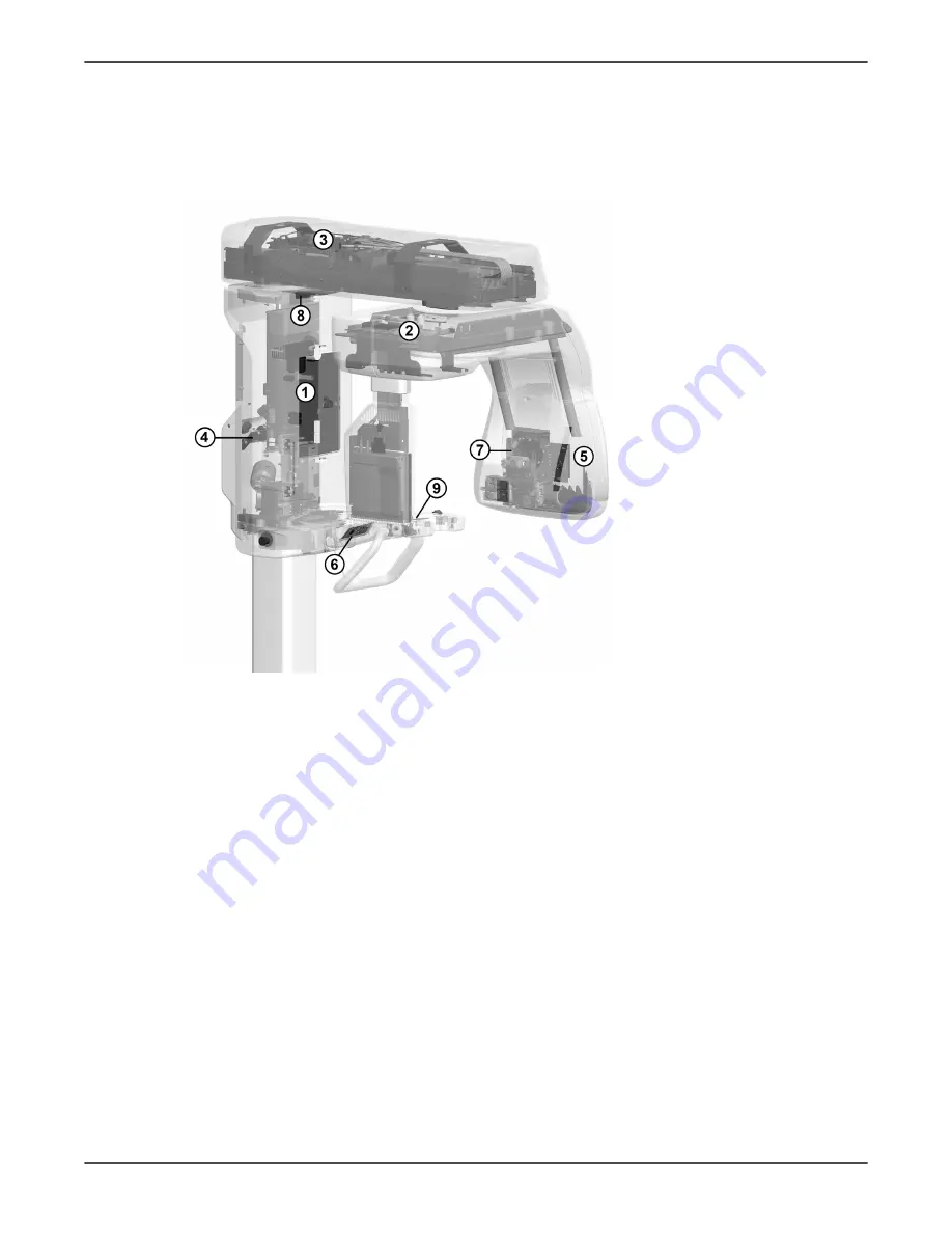
4.3.1 Circuit board locations
1.
i4000 Power Supply
board
2.
i2000 Image Capture
Board
3.
i3000 Main Control
Board
4.
i4100 Back panel
board
5.
i5000 Cascade board
(in the Tubehead
assembly)
6.
i6000 User interface
board
7.
i7000 Tubehead
interface board (in the
Tubehead assembly)
8.
i8000 LED indicator
board
9.
i9000 Chin rest
sensor board
4.3.2 Circuit boards overview
The OP 3D HW structure is based on three main electrical boards. Each board
implements certain control functions, such as exposure control and motion control, and
they interact with each other through the communication buses.
The main boards are:
i2000 Image Capture Board
i3000 Main Control Board
i4000 Power Supply board
The device also contains seven smaller boards:
i4100 Back panel board
i5000 Cascade board
(part of the tube head)
i6000 User interface board
i7000 Tubehead interface board
(part of the tube head)
i8000 LED indicator board
i9000 Chin rest sensor board
ORTHOPANTOMOGRAPH
™
OP 3D
19


