DS Series PBX Technical Reference And Installation Guide
207
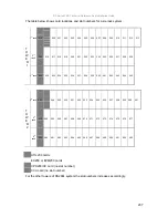
The table below shows card locations and slot numbers for a six-rack system:
1
st
rack 014
000
001
002
003
004
005
006
007
008
009
010
011
012
013
2
nd
rack
030
016
017
018
019
020
021
022
023
024
025
026
027
028
029
T
O
W
E
R
1
3
rd
rack 046
032
033
034
035
036
037
038
039
040
041
042
043
044
045
4
th
rack 062
048
049
050
051
052
053
054
055
056
057
058
059
060
061
5
th
rack
078
064
065
066
067
068
069
070
071
072
073
074
075
076
077
T
O
W
E
R
2
6
th
rack
094
080
081
082
083
084
085
086
087
088
089
090
091
092
093
UTIL200 cards
EX200 or EVM200 cards
CPU200/CC card (no slot number)
CCU card (no slot number)
For the other towers of DS200L system the slot numbers increases accordingly.
Summary of Contents for DS200
Page 1: ...11 2010 TECHNICAL REFERENCE AND INSTALLATION GUIDE PBX DS SERIES...
Page 2: ...DS SERIES PBX TECHNICAL REFERENCE AND INSTALLATION GUIDE NOVEMBER 2010...
Page 17: ...DS Series PBX Technical Reference And Installation Guide 7...
Page 69: ...DS Series PBX Technical Reference And Installation Guide 59...
Page 80: ...70...
Page 222: ...11 2010...


