134
4- The back and side covers are removed, after unlocking them, by lifting them by
approximately 10 cm. in such a manner that their paint is not scratched.
5- While removing the covers, one must watch out for the grounding cables that are
between the covers and the main frame, so that they should not break off. The cables
must be removed from the covers together with their tags and safely kept away against
any damage during the mounting of the exchange into the cabinet.
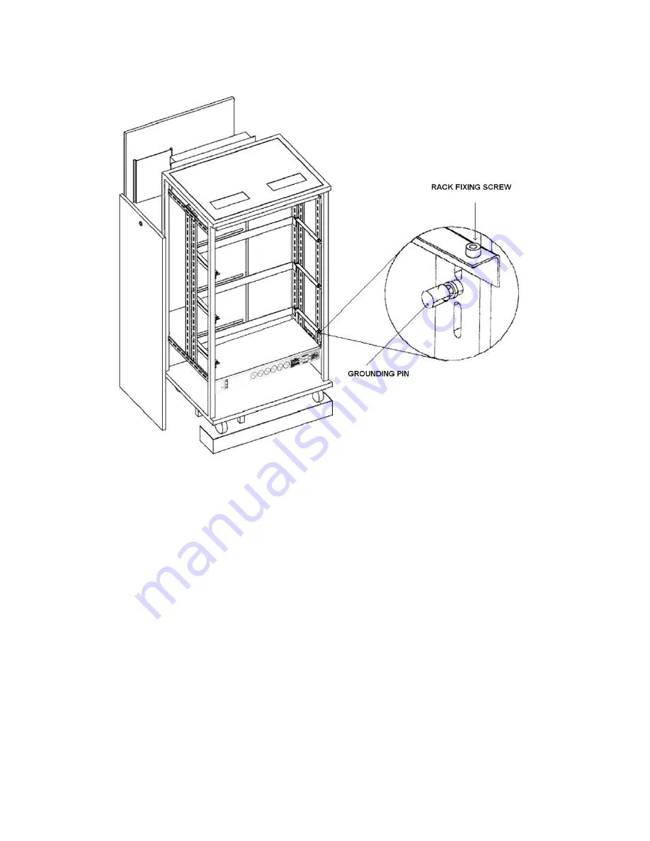
6- The main rack and the auxiliary racks are pushed to slide on slots one by one until the
holes of the removed stopping screws appear. Then the stopping screws are replaced,
so that the racks would not slide along the slots.
7- The cable panels are opened from the back in order to facilitate access.
8- Connections among the main rack and the auxiliary racks, as well as the inter-rack
ground connection, are made. To make those connections, first, the BPL200-FC and
BPLSPS-FC connection cables, which come with the auxiliary rack hardware on delivery,
are used. These are three cables. Two BPL200-FC's (34-pin flat cable) are used to
connect the BPL200 backplanes to each other and the BPLSPS-FC (5-wire cable) is
used to connect the BPL200-SPS backplanes. In order to connect the backplanes to
each other:
a) First of all, one end of each BPL200-FC is attached to the BPL200-MAIN backplane
of the main rack that has been placed to the bottom.
b) The free ends of the BPL200-FC cables are extended to the second rack through the
cable holes that correspond to the upper panel on the back of the first rack and the
Summary of Contents for DS200
Page 1: ...11 2010 TECHNICAL REFERENCE AND INSTALLATION GUIDE PBX DS SERIES...
Page 2: ...DS SERIES PBX TECHNICAL REFERENCE AND INSTALLATION GUIDE NOVEMBER 2010...
Page 17: ...DS Series PBX Technical Reference And Installation Guide 7...
Page 69: ...DS Series PBX Technical Reference And Installation Guide 59...
Page 80: ...70...
Page 222: ...11 2010...


