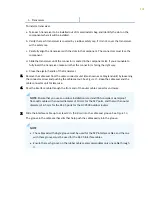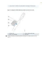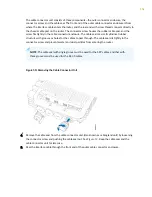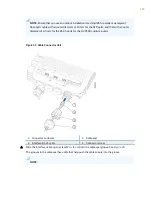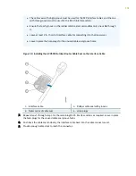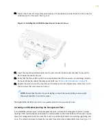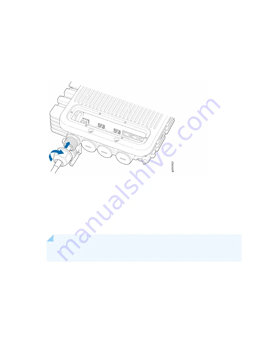
Pull the cable with a torque of 16 lb-in. (1.8 Nm) to ensure that the cable sits tightly inside the cable
connector unit. Also, visually examine the cable and the groove to ensure that there is no gap left,
and that the cable sits properly in the groove.
Figure 48: Installing the ACX500 Outdoor Router Connector Screw
11. Repeat steps
3
through step
10
for the remaining interface cables, as required.
12. Insert the interface cables into the respective transceivers. See
"Replacing a Fiber-Optic Cable" on
. Use the interface port chamber to snap in the SFP cable into the transceiver.
13. Verify that the status LEDs on the front panel indicate that the transceiver is functioning correctly.
For more information about the component LEDs, see
"LEDs on ACX500 Routers" on page 59
.
14. Replace the metal cover of the interface port chamber back to its original place, and secure it with
the six screws that were removed in step
1
.
NOTE: Ensure that the metal cover sits tightly on top of the router. Failing to do so might
allow dust and water to enter the router.
The Gigabit Ethernet SFP ports are now weatherproof and are ready to use.
Weatherproofing the Interface Ports—Gigabit Ethernet RJ-45
To access and weatherproof the Gigabit Ethernet RJ-45 interface ports and cables:
1.
Unscrew and remove the six screws from the metal cover on top of the router that covers the
interface port chamber. Keep the screws for later use.
150


