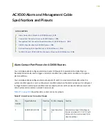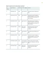
Table 27: Alarm Contact Connector Pinouts
(Continued)
Pin
Number
Signal Definition
Direction
CLI Port Mapping
Function
10
ALARM_OUT3_NO/NC
Output
Reserved for
Minor alarm
External alarm output 3 (this pin is
connected to Pin 5 in closed condition)
11
ALARM_OUT0_NO/NC
Output
Output Alarm
Port 0
External alarm output 0 (this pin is
connected to Pin 12 in closed
condition)
12
ALARM_OUT0_REF
Output
Output Alarm
Port 0
External alarm output 0 (this pin is
connected to Pin 11 in closed
condition)
13
ALARM_OUT1_NO/NC
Output
Output Alarm
Port 1
External alarm output 1 (this pin is
connected to Pin 14 in closed
condition)
14
ALARM_OUT1_REF
Output
Output Alarm
Port 1
External alarm output 1 (this pin is
connected to Pin 13 in closed
condition)
15
ALARM_OUT2_NO/NC
Output
Reserved for
Major alarm
External alarm output 2 (this pin is
connected to Pin 9 in closed condition)
Console Port Connector Pinout on ACX500 Routers
The port labeled CONSOLE on the front panel is an asynchronous serial interface that accepts an RJ-45
connector. Use a cable with the pinouts described in
to connect the Routing
Engine to a console management device.
NOTE: You must use a shielded twisted pair (STP) cable for both outdoor and indoor router
deployments.
103

