


41
Belts
New belts should be re-checked after 24 hours of
operation. On multiple belt adjustable pulleys, the pitch
depth should be checked to insure identical belt travel,
power transfer and wear. Adjustable motor bases are
provided for belt adjustment.
Motor pulleys and blower shaft pulleys are locked
in position with either set screws or split taper lock
bushings. All set screws and/or taper lock bolts must
be checked for tightness and alignment before putting
equipment into operation.
An incorrectly aligned and tensioned belt can
substantially shorten belt life or overload blower and
motor bearings, shortening their life expectancy. A belt
tensioned too tightly can overload the motor electrical,
causing nuisance tripping of the motor overloads and/or
motor failure and/or shaft failure.
Belt Replacement
Always replace belts as a set. Follow the steps below
to replace belts:
1. Release the tension on the belts by loosening the
adjusting nuts on the fan motor.
2. Remove old belts and recheck the sheave alignment
with a straight edge.
3. Install the new belts on the sheaves.
Never place the belts on the sheaves by using a
screwdriver to pry the belt over the rim of the sheave.
This will damage the belts permanently.
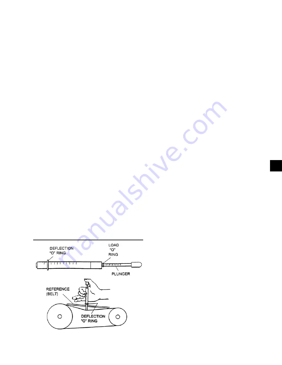
Belt Tensioning:
A Browning Belt tension gauge is used in Fig. 4 to
properly tension belts.
Filter Drier Replacement
The filter/drier should be replaced any time a refrigerant
system is open. The Versecon unit comes with sealed
type (non-replaceable) cores as standard. The refrigerant
would need to be recovered with a recovery machine to
replace the filter/drier.
Supply Fan
In the unlikely event that the supply fan would need to
be replaced the following procedure would need to be
followed:
1. On the 12 to 32 ton units, access to the rear bearing
is through the upper panel on the right hand side
of the condenser / compressor section. Once the
panel is removed it will expose a patch plate in
the transition wall between the evaporator coil and
the supply blower. Removal of this patch allows
access to the bearing.
On the 39 to 90 ton units, access to the bearing is
gained by removing a patch plate on the top of the
condenser / compressor section of the unit.
2. Thoroughly clean the shaft of all grease and rust
inhibitor. Be careful not to contaminate the bearing
grease. Use emery cloth to remove all rust or the
wheel may become “locked” to the shaft.
3. Loosen and remove the setscrews on both bear-
ing locking collars. Inspect and, if necessary,
replace.
4. Loosen and remove the two setscrews from the
Condenser / Compressor side of the supply fan
wheel.
5. Using a rubber mallet or brass bar, slowly drive the
shaft in one direction until the set screw marks on
the shaft are fully exposed. File the marks com-
pletely smooth. Drive the shaft in the opposite
direction and file smooth the setscrew marks.
FIG. 4 – BELT TENSIONING GAUGE
LD06354
4
JOHNSON CONTROLS
FORM 145.05-NOM1 (708)
Summary of Contents for York VERSECON YSWD 012
Page 12: ...12 JOHNSON CONTROLS FORM 145 05 NOM1 708 THIS PAGE INTENTIONALLY LEFT BLANK ...
Page 58: ...58 JOHNSON CONTROLS FORM 145 05 NOM1 708 THIS PAGE INTENTIONALLY LEFT BLANK ...
Page 106: ...106 JOHNSON CONTROLS FORM 145 05 NOM1 708 THIS PAGE INTENTIONALLY LEFT BLANK ...
Page 112: ...112 JOHNSON CONTROLS FORM 145 05 NOM1 708 THIS PAGE INTENTIONALLY LEFT BLANK ...


