4 - 1
General Description
The alternator is a three phase generator having a rotating
field winding and static power windings.
When the start switch is turned on, current from the battery
flows by way of the 'No Charge' warning light to the field
winding. This creates a magnetic field which supplements the
residual magnetism in the rotor poles. As the engine is
started, the fan belt drives the rotor and alternating current is
generated in the power windings as they are cut by the
rotating magnetic field. Output is controlled by a solid state
regulator which varies the field current in accordance with
electrical demand.
Service Precautions
a
Ensure that the battery negative terminal is connected to
the earthing cable.
b
Never make or break connections to the battery or
alternator, or any part of the charging circuit whilst the
engine is running. Disregarding this instruction will result
in damage to the regulator or rectifying diodes.
c
Main output cables are 'live' even when the engine is not
running. Take care not to earth connectors in the
moulded plug if it is removed from the alternator.
d
During arc welding on the machine, protect the alternator
by removing the moulded plug.
e
If slave starting is necessary, connect the second battery
in parallel without disconnecting the vehicle battery from
the charging circuit. The slave battery may then be
safely removed after a start has been obtained. Take
care to connect batteries positive to positive, negative to
negative. See also note
b
.
Charging Circuit Check
Ensure that all battery and alternator connections are in
place, secure and making good metal - to - metal contact,
especially the 'earth' connections to chassis and engine.
Adjust the alternator drive belt tension if necessary and make
sure that the battery is well charged.
Turn the start switch to the ON position.
'Oil pressure' and 'No charge' warning lights should glow.
If any light fails, proceed to Check 1.
Start the engine; all warning lights should extinguish rapidly.
If the 'No charge' warning light remains ON proceed to Check
2.
If the oil pressure warning remains on STOP ENGINE
IMMEDIATELY and investigate the engine lubrication
system.
Check 1
With start switch 'ON' try the heater motor and screen wiper.
If they operate normally, check the warning light bulb for
blown filament.
Simultaneous failure of all items indicates a fault at the start
switch. Check for cable disconnection before condemning
the switch itself.
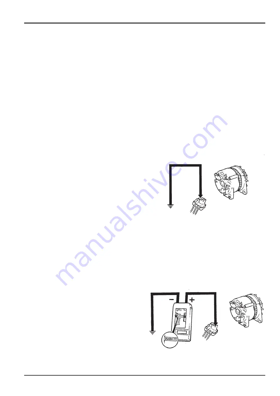
If the 'No charge' warning bulb is in good order, withdraw the
triple plug from the back of the alternator. Make a temporary
connection between the SMALL terminal in the plug and
earth as shown below. If the 'No Charge' warning bulb still
fails to light, check the brown/black cable for continuity. If the
bulb now lights, check the alternator for a defective regulator
(see
Alternator Charging Test
).
Check 2
Stop the engine and turn the starter switch to OFF.
Withdraw the alternator plug and connect the test meter
(Service Tool 892/00281) between the large terminals and
'earth'. With the selected position as shown, the meter should
show battery voltage. If the reading is zero, check the brown
cables for continuity, particularly at the starter terminals.
If the voltage is correct, check the alternator as on page 4 -
2.
Section C
Electrics
9803/8500
Section C
4 - 1
Issue 1
Alternator
Summary of Contents for ROBOT 150
Page 2: ......
Page 21: ...5 2 Safety Decals cont d Section 2 Care and Safety 9803 8500 Section 2 5 2 Issue 2...
Page 77: ...Attachments Section A Section A 7 7 9803 8500 Issue 1 Backhoe...
Page 97: ...4 3 Section C Electrics 9803 8500 Section C 4 3 Issue 1 Alternator S213570...
Page 123: ...1 1 Section D Controls 9803 8500 Section D 1 1 Issue 1 Safety Restraint Bar S168160 1...
Page 125: ...2 1 Section D Controls 9803 8500 Section D 2 1 Issue 1 Throttle Controls S168150D...
Page 142: ...Hydraulics 9803 8500 Issue 1 4 1 4 1 Descriptions Section E Section E...
Page 145: ...Hydraulics 9803 8500 Issue 2 5 2 5 2 Descriptions Section E Section E...
Page 146: ...Hydraulics 9803 8500 Issue 2 5 3 5 3 Descriptions Section E Section E...
Page 149: ...Hydraulics 9803 8500 Issue 2 5 6 5 6 Descriptions Section E Section E...
Page 152: ...Hydraulics 9803 8500 Issue 1 5 9 5 9 Descriptions Section E Section E...
Page 163: ...10 1 Section E Hydraulics 9803 8500 Section E 10 1 Issue 1 Pumps 168150...
Page 165: ...10 3 Section E Hydraulics 9803 8500 Section E 10 3 Issue 1 Pumps 168030...
Page 167: ...10 5 Section E Hydraulics 9803 8500 Section E 10 5 Issue 1 Pumps 168160...
Page 175: ...11 1 Section E Hydraulics 9803 8500 Section E 11 1 Issue 2 Pumps 167750...
Page 179: ...13 1 Section E Hydraulics 9803 8500 Section E 13 1 Issue 1 Drive Motors 167720 S167720A...
Page 183: ...13 5 Section E Hydraulics 9803 8500 Section E 13 5 Issue 1 Drive Motors S243720 X X S243870...
Page 212: ...18 1 Section E Hydraulics 9803 8500 Section E 18 1 Issue 2 Valves S204980 X X 3 B A 4 2 1 5...
Page 215: ...20 1 Section E Hydraulics 9803 8500 Section E 20 1 Issue 1 Servo Joysticks S167960...
Page 217: ...20 3 Section E Hydraulics 9803 8500 Section E 20 3 Issue 1 Servo Joysticks 167950...
Page 221: ...23 3 Section E Hydraulics 9803 8500 Section E 23 3 Issue 1 Rams S167800...
Page 241: ...1 2 Section F Transmission 9803 8500 Section F 1 2 Issue 2 Tyres and Wheels 167861 167811...
Page 243: ...1 4 Section F Transmission 9803 8500 Section F 1 4 Issue 2 Tyres and Wheels 167851...
Page 253: ...2 1 Section K Engine 9803 8500 Section K 2 1 Issue 1 Removal and Replacement S167990...


