Controls/Features
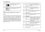
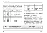
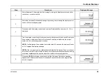
Warning Indicators
The instrument panel gauge cluster contains 25 individual LED
warning indicators. These indicators are used to monitor vehicle
operation and indicate a WARNING or STOP condition. These
warning indicators are driven by the software in the instrument
panel gauge cluster.
At ignition, the warning indicators will
illuminate for 8 to 10 seconds, as part of the vehicle power-up
sequence.
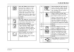
Item
No.
Item
Description
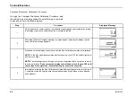
1
Illuminates Yellow when the intake
heaters and glow plugs are in operation
and special starting procedures are
required. Refer to the Starting Switch
paragraph in the Vehicle Operation
section for more information.
2
Illuminates Yellow to alert driver that
vehicle idle shutdown timer will turn
engine off in 30 seconds.
3
Illuminates Yellow. Used in conjunction
with other Warning Indicators or General
Text and Warning Messages and may
be accompanied by an audible alarm
to indicate an Alert condition to the
operator.
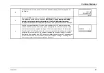
4
Illuminates Yellow. Used in conjunction
with other Warning Indicators or General
Text and Warning Messages to indicate
an Alert condition to the operator.
5
Illuminates Red Used in conjunction with
other Warning Indicators or General Text
and Warning Messages to indicate a red
STOP alert.
6
Not Used.
7
Illuminates Red when the parking brake
is applied. If the brake warning indicator
does not illuminate, or if it stays on with
the parking brake not engaged, seek
service immediately.
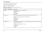
8
Illuminates Green to assist operators
in determining when it is appropriate to
shift the transmission to a higher gear in
order to maximize driving fuel economy.
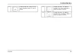
9
Illuminates Yellow to indicate engine
brake capability has been activated.
10
Illuminates Yellow when a trailer antilock
brake system malfunction has been
detected. If the ABS indicator stays
illuminated or continues to flash, have
the system serviced immediately.
48
3878859R2
Summary of Contents for ProStar+ Eagle Series.
Page 4: ...Operator s Manual ProStar Series Printed in the United States of America 3878859R2 ...
Page 12: ...Table of Contents Section 10 Index Index 235 viii 3878859R2 ...
Page 26: ...Model Description Exterior Components 14 3878859R2 ...
Page 28: ...Model Description 16 3878859R2 ...
Page 59: ...Controls Features 3878859R2 47 ...
Page 70: ...Controls Features Declination Zone Map 58 3878859R2 ...
Page 93: ...Controls Features Center Dash Panel Wing Panel 3878859R2 81 ...
Page 128: ...Sleeper Features 116 3878859R2 ...
Page 182: ...Operation 170 3878859R2 ...
Page 241: ...Maintenance Intervals and Specifications Typical Interior Fuse Panel Layout 3878859R2 229 ...
Page 262: ...Index 250 3878859R2 ...

