Maintenance Instructions
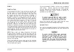
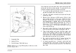
1.
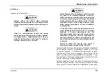
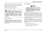
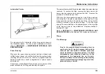
Deaeration Tank
2.
Vented Fill Cap
3.
COLD MIN and COLD MAX Lines
NOTE: Vented fill cap may differ slightly in location on tank
between engine sizes.
To function properly, the coolant system must be completely filled
with coolant and all air must be expelled. To accomplish this, the
following procedures should be carefully completed:
1.
Turn on ignition without starting the vehicle. This opens the
electrically actuated LTR coolant flow valve.
2.
Fully open cab heater coolant shut-off valves and coolant
system vent valve.
3.
Remove fill cap and pour a 50/50 mixture (75/25 if it has
been flushed with water) of the proper (Nitrite-Free Shell
Rotella® Ultra Extended Life Coolant) coolant concentrate
and demineralized or distilled water into the de-aeration
tank. A 50/50 coolant mixture will achieve a -34° F (-37° C)
freeze point. A 53/47 coolant mixture will achieve a -40° F
(-40° C) freeze point. The first pour should reach to the top
of the reservoir fill neck.
4.
Because the radiator fills slowly, it is important to continue to
top off the system for two minutes following the initial fill.
5.
Close coolant system vent valve, start the engine, and
continue to add enough coolant to keep the coolant level
between the COLD MIN and COLD MAX levels marked on
the deaeration tank. Replace the deaeration tank cap tightly
after adding make-up coolant for two minutes.
6.
Run engine at governed speed until engine fan has fully
engaged for 5 minutes. Do not exceed 220° F (104° C).
7.
Let engine completely cool.
Re-check coolant level and
concentration/freeze point with a refractometer and top off
as needed to achieve a coolant level at the COLD MAX line
when cold.
3878859R2
193
Summary of Contents for ProStar+ Eagle Series.
Page 4: ...Operator s Manual ProStar Series Printed in the United States of America 3878859R2 ...
Page 12: ...Table of Contents Section 10 Index Index 235 viii 3878859R2 ...
Page 26: ...Model Description Exterior Components 14 3878859R2 ...
Page 28: ...Model Description 16 3878859R2 ...
Page 59: ...Controls Features 3878859R2 47 ...
Page 70: ...Controls Features Declination Zone Map 58 3878859R2 ...
Page 93: ...Controls Features Center Dash Panel Wing Panel 3878859R2 81 ...
Page 128: ...Sleeper Features 116 3878859R2 ...
Page 182: ...Operation 170 3878859R2 ...
Page 241: ...Maintenance Intervals and Specifications Typical Interior Fuse Panel Layout 3878859R2 229 ...
Page 262: ...Index 250 3878859R2 ...

