Operation
WARNING
DO NOT Check Battery Condition By Shorting
(Flashing) Across Terminals.
Failure to follow
this warning could result in property damage,
personal injury, or death.
When working around the terminals and battery, use extra care
to avoid shorting. A good practice is to use insulated pliers and
screwdrivers.
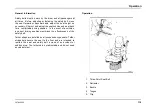
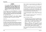
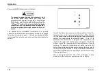
BATTERY ON Indicator
1.
Left Side of Dash
2.
BATTERY ON Indicator
If the vehicle is equipped with a battery disconnect switch, an
optional BATTERY ON indicator may be located on the left side
of the instrument panel gauge cluster. The green BATTERY ON
indicator will illuminate any time the battery disconnect switch is
in the ON position (batteries connected) regardless of the key
state. This indicator can easily be viewed with the driver door
open and without entering the vehicle.
Circuit Breakers, Fuses and Fusible Links
WARNING
Electrical circuits are designed with a particular
wire gauge to meet the fuse and circuit breaker
current rating. Do not increase size of fuse or
circuit breaker or change type of breaker supplied
with your truck. To do so could cause wiring to
overheat and possibly burn, resulting in a fire
which could cause property damage, personal
injury, or death.
•
Electrical circuits are protected either by the electrical
system controller, circuit breakers, fuses or fusible links.
For the size and location of circuit breakers, fuses and
fusible links, please refer to the Maintenance Intervals and
Specifications section of this manual.
•
Fusible links consist of a length of lighter gauge wire in a
circuit. In case of a short or overload, the fusible link opens
(burns out) to protect the remainder of the circuit. Repair
consists of installing a new fusible link with the same gauge
wire as the opened fusible link.
3878859R2
131
Summary of Contents for ProStar+ Eagle Series.
Page 4: ...Operator s Manual ProStar Series Printed in the United States of America 3878859R2 ...
Page 12: ...Table of Contents Section 10 Index Index 235 viii 3878859R2 ...
Page 26: ...Model Description Exterior Components 14 3878859R2 ...
Page 28: ...Model Description 16 3878859R2 ...
Page 59: ...Controls Features 3878859R2 47 ...
Page 70: ...Controls Features Declination Zone Map 58 3878859R2 ...
Page 93: ...Controls Features Center Dash Panel Wing Panel 3878859R2 81 ...
Page 128: ...Sleeper Features 116 3878859R2 ...
Page 182: ...Operation 170 3878859R2 ...
Page 241: ...Maintenance Intervals and Specifications Typical Interior Fuse Panel Layout 3878859R2 229 ...
Page 262: ...Index 250 3878859R2 ...

