Processor Thermal/Mechanical Information
20
Thermal and Mechanical Design Guidelines
Section
3.1). The intercept on the thermal profile assumes a maximum ambient
operating condition that is consistent with the available chassis solutions.
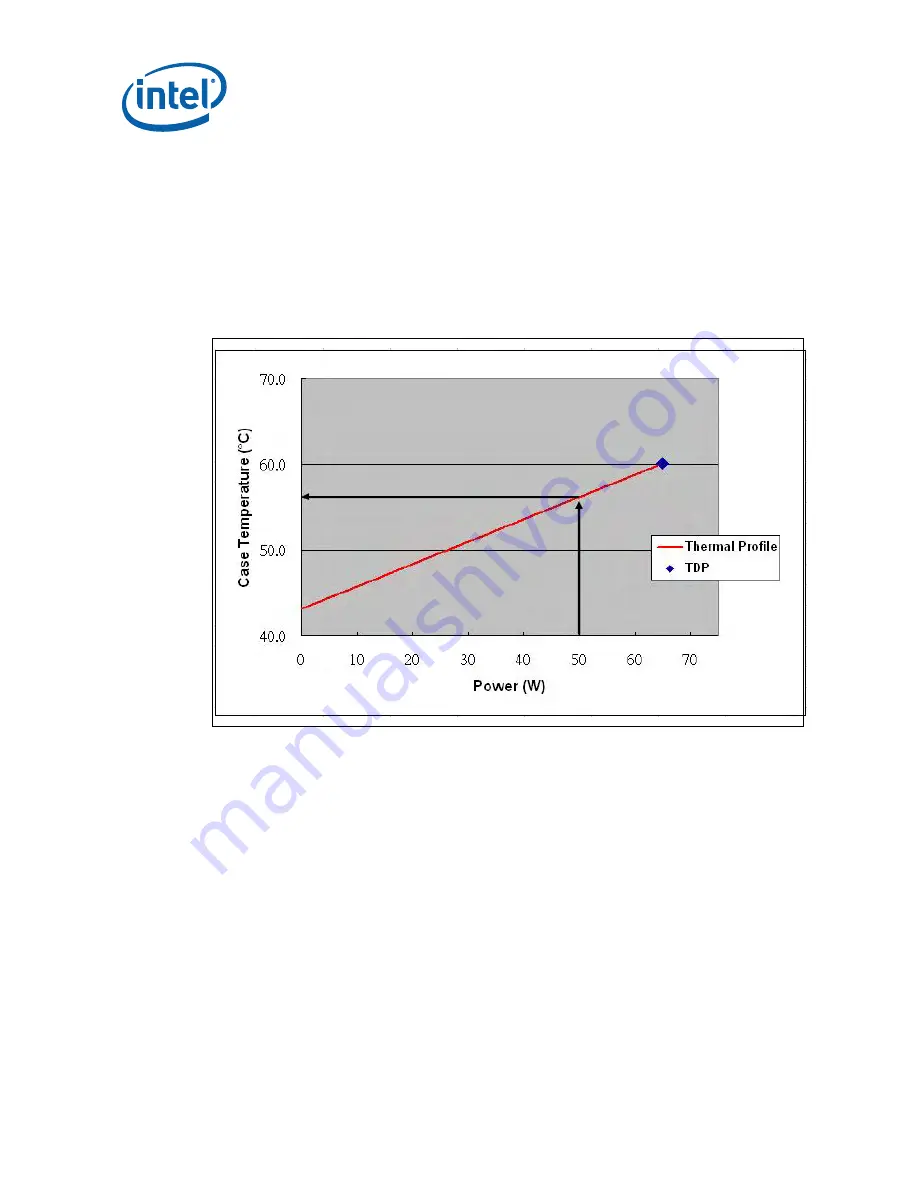
To determine compliance to the thermal profile, a measurement of the actual
processor power dissipation is required. The measured power is plotted on the
Thermal Profile to determine the maximum case temperature. Using the example in
Figure
®
Core
™
2 Duo processor with 4 MB cache at Tc-max of 60.1 °C
dissipating 50 W, the maximum case temperature is 56.2 °C. See the datasheet for
the thermal profile.
Figure
2-3. Example Thermal Profile
2.2.3
T
CONTROL
T
CONTROL
defines the maximum operating temperature for the digital thermal sensor
when the thermal solution fan speed is being controlled by the digital thermal sensor.
The T
CONTROL
parameter defines a very specific processor operating region where fan
speed can be reduced. This allows the system integrator a method to reduce the
acoustic noise of the processor cooling solution, while maintaining compliance to the
processor thermal specification.
Note:
The T
CONTROL
value for the processor is relative to the Thermal Control Circuit (TCC)
activation set point which will be seen as 0 via the digital thermal sensor. As a result
the T
CONTROL
value will always be a negative number. See Chapter
discussion the thermal management logic and features and Chapter
7 on Intel
®
Quiet
System Technology (Intel
®
QST).
The value of T
CONTROL
is driven by a number of factors. One of the most significant of
these is the processor idle power. As a result a processor with a high (closer to 0 )
Summary of Contents for Celeron Dual-Core E1000 Series
Page 10: ...10 Thermal and Mechanical Design Guidelines...
Page 26: ...Processor Thermal Mechanical Information 26 Thermal and Mechanical Design Guidelines...
Page 68: ...ATX Thermal Mechanical Design Information 68 Thermal and Mechanical Design Guidelines...
Page 86: ...Heatsink Clip Load Metrology 86 Thermal and Mechanical Design Guidelines...
Page 88: ...Thermal Interface Management 88 Thermal and Mechanical Design Guidelines...
Page 120: ...Legacy Fan Speed Control 120 Thermal and Mechanical Design Guidelines...
Page 126: ...Fan Performance for Reference Design 126 Thermal and Mechanical Design Guidelines...
Page 127: ...Fan Performance for Reference Design Thermal and Mechanical Design Guidelines 127...


