ICU Medical LifeCare PCA Technical & Service Manual Download Page 12

SECTION 1 INTRODUCTION

LifeCare PCA

1 - 2

Technical Service Manual

Section 7 Replaceable Parts and Repairs

Section 8 Specifications

Section 9 Drawings

Appendices

If a problem in device operation cannot be resolved using the information in this manual,

contact ICU Medical 

(see Section 6.1)

.

Specific instructions for operating the device are contained in its respective


System

Operating Manual

.

The terms “infusion system”, “infuser”, and “device” are used interchangeably throughout
the manual.

Figures are rendered as graphic representations to approximate actual product.
Therefore, figures may not exactly reflect the product. Screen representations
are examples only, and do not necessarily reflect the most current configuration.

1.3

CONVENTIONS

The conventions listed in 

Table 1-1

 are used throughout this manual.

Throughout this manual, warnings, cautions, and notes are used to emphasize important
information, as follows:

Note:

A note highlights information that helps explain a concept or procedure. 

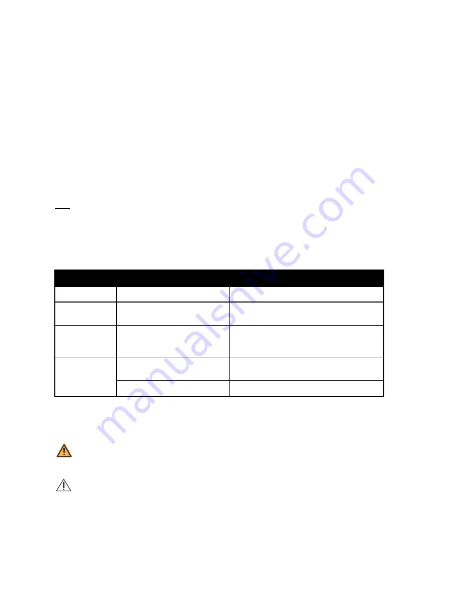
Table 1-1. Conventions

Convention

Application

Example

Italic

Reference to a section, figure,

table, website, or publication

(see Section 6.1)

[ALL CAPS]

ALL CAPS

In-text references to keys, 

touchswitches, and display 

messages

[START]

LOW BATTERY

Bold

Emphasis

CAUTION: Use proper ESD grounding 

techniques when handling components.

Screen displays

Select 

Set Time and Date

.

WARNING: A WARNING CONTAINS SPECIAL SAFETY EMPHASIS AND MUST
BE OBSERVED AT ALL TIMES. FAILURE TO OBSERVE A WARNING MAY RESULT
IN PATIENT INJURY AND BE LIFE-THREATENING.

CAUTION:

A CAUTION usually appears in front of a procedure or statement.

It contains information that could prevent hardware failure, irreversible
damage to equipment, or loss of data.

Summary of Contents for LifeCare PCA

Page 1: ...600 N Field Drive Lake Forest Illinois 60045 USA 430 97357 004 A 2018 06 Technical Service Manual Compatible with ICU Medical MedNet For use with list number 20837 04 and list number 20709 04 upgrade...

Page 2: ...LifeCare PCA Technical Service Manual This page intentionally left blank...

Page 3: ...ed cleaning and disinfecting instructions throughout the manual Updated contact information throughout the manual Clarified references to the lithium coin cell battery throughout the manual Updated re...

Page 4: ...CHANGE HISTORY Technical Service Manual ii LifeCare PCA This page intentionally left blank...

Page 5: ...ING MANUAL 3 1 Section 4 INFORMATION FOR LEGACY LIFECARE PCA INFUSERS UPGRADED WITH 7 X SOFTWARE 4 1 4 1 IEC 60601 1 COMPLIANCE 4 2 4 2 IEC 60601 1 2 COMPLIANCE 4 2 4 3 FLUID INGRESS PROTECTION RATING...

Page 6: ...N 5 21 5 5 3 AC POWER CORD INSPECTION AND TEST 5 23 5 5 4 FRONT ENCLOSURE REAR ENCLOSURE CRADLE ASSEMBLY AND SECURITY DOOR INSPECTION AND TEST 5 25 5 5 5 RUBBER FOOT PAD INSPECTION 5 27 5 5 6 POLE CLA...

Page 7: ...4 CRADLE ASSEMBLY REPLACEMENT 7 15 7 3 8 5 MECHANISM LEVER ARM REPLACEMENT 7 16 7 3 8 6 DOOR LATCH ASSEMBLY REPLACEMENT 7 17 7 3 8 7 DOOR LOCK ASSEMBLY REPLACEMENT 7 18 7 3 8 8 HANDLE GASKET AND ENCLO...

Page 8: ...CONTENTS LifeCare PCA vi Technical Service Manual Section 9 DRAWINGS 9 1 Appendix A 1...

Page 9: ...1 Figure 5 15 Barcode Reader Assembly 5 33 Figure 5 16 Vial Injector Position for Stuck Injector Switch Pin Test 5 36 Figure 5 17 LifeCare PCA Self Test Screens 5 37 Figure 5 18 Ethernet Connectivity...

Page 10: ...Measurements 5 42 Table 6 1 Operational Alarm Messages 6 3 Table 6 2 Error Codes Requiring Technical Service 6 6 Table 6 3 Troubleshooting with the PVT 6 12 Table 9 1 Illustrated Parts Breakdown 9 1...

Page 11: ...ol 802 11 a b g ICU Medical MedNet networked application software allows a facility to customize and download a Drug Library for use with the infusion system Before using the software see the ICU Medi...

Page 12: ...ons listed in Table 1 1 are used throughout this manual Throughout this manual warnings cautions and notes are used to emphasize important information as follows Note A note highlights information tha...

Page 13: ...ons used in this manual are as follows A Ampere AC Alternating current ADC Analog to digital converter BCR Barcode reader CE Connectivity engine CMOS Complementary metal oxide semiconductor CPU Centra...

Page 14: ...nt controlled analgesia PCL Power control logic psi Pounds per square inch PVT Performance verification test PWA Printed wiring assembly RAM Random access memory ROM Read only memory RTC Real time clo...

Page 15: ...nvironment set the device so that it is temporarily not delivering fluid Disappearance of the abnormality indicates that it was probably caused by electronic noise generated by the infuser Proper setu...

Page 16: ...INSTALLATION Accessory equipment connected to the analog and digital interfaces must be certified according to the respective IEC standards e g IEC 60601 1 for medical equipment If in doubt contact I...

Page 17: ...rade 120 VAC 50 60 Hz receptacle Verify the AC plug indicator on the front panel is illuminated Note If the quality of earth grounding source is in doubt use battery power Note When the AC plug indica...

Page 18: ...lect SETTINGS on this screen to view the Select Setting to Change menu and press the TIME DATE softkey The screen displays WARNING CHANGING THE DATE OR TIME WILL CLEAR ALL TOTALS 4 Press the CONTINUE...

Page 19: ...E 6 After the power up RAM test is completed the infuser displays the Biomed Mode Main Menu screen Press the MAINTENANCE softkey 7 Press the SET VOLUME softkey WARNING CHECK THAT THE ALARM VOLUME LEVE...

Page 20: ...ning instructions in Section 5 2 3 through Section 5 2 11 1 11 SUSPECTED CYBERSECURITY EVENT OR THREAT The section contains information on the recommended procedure upon detecting a suspected cybersec...

Page 21: ...s Warranty product returned to ICU Medical must be properly packaged and sent freight prepaid The foregoing warranty shall be void in the event the product has been misused damaged altered or used oth...

Page 22: ...SECTION 2 WARRANTY LifeCare PCA 2 2 Technical Service Manual This page intentionally left blank...

Page 23: ...1 LifeCare PCA Section 3 SYSTEM OPERATING MANUAL A copy of the System Operating Manual is included with every LifeCare PCA with ICU Medical MedNet infusion system If a copy is not available contact I...

Page 24: ...SECTION 3 SYSTEM OPERATING MANUAL LifeCare PCA 3 2 Technical Service Manual This page intentionally left blank...

Page 25: ...Back cover Section 4 1 IEC 60601 1 Compliance IEC 60601 1 2 Compliance Section 1 8 Electromagnetic Compatibility Section 4 2 IEC 60601 1 2 Compliance Fluid Ingress Protection Rating Back cover Section...

Page 26: ...007 as specified in Section 1 8 Electromagnetic Compatibility the following applies The LifeCare PCA has been tested and found to comply with electromagnetic com patibility EMC limits as specified in...

Page 27: ...gs on the DPM To perform the occlusion test proceed as follows 1 Connect the distal end of the LifeCare PCA set to the DPM through a three way stopcock Set the three way stopcock to air 2 Verify the D...

Page 28: ...d 9 Press and hold the PURGE softkey until flow is seen at the three way stopcock then release the PURGE softkey 10 Verify the PURGE COMPLETE message is displayed Check for air in line and assure the...

Page 29: ...ion switch closed check for the following three possibilities The leaf spring may be damaged or bent Replace it if necessary The 2 24 screw holding the leaf spring to the mechanism top support may be...

Page 30: ...opcock valve Loosen the set screw on the thumb nut and turn the thumb nut clockwise to tighten and repeat Step 4 12 If the occlusion alarm does not sound at or before 20 psi relieve the fluid pressure...

Page 31: ...pendant jack assembly 6 Install the replacement patient pendant jack assembly in the exact reverse order of removal Secure the patient pendant jack harness to the rear enclosure harness assembly with...

Page 32: ...SECTION 4 INFORMATION FOR LEGACY LIFECARE PCA INFUSERS UPGRADED WITH 7 X SOFTWARE LifeCare PCA 4 8 Technical Service Manual This page intentionally left blank...

Page 33: ...e instructions should also be used to prepare the infuser for initial use on a patient storage repair or preventive maintenance Cleaning and disinfecting the infuser prevents build up of contaminants...

Page 34: ...le 5 1 Note At the time of publication ICU Medical recommends only the cleaning solution in Table 5 1 For updated listings of approved cleaners visit www icumed com CAUTION Use only recommended cleani...

Page 35: ...ning the infuser Note If the infuser enclosure is cracked or damaged clean and disinfect the infuser then return it to the Biomed technician to replace the damaged enclosure see Section 7 3 3 5 2 4 GE...

Page 36: ...ompletely removed Non Abrasive Brush 1 Wearing gloves dampen the brush in the cleaning solution and gently brush seams and dried soil 2 Use a cloth dampened in the cleaning solution or cleaning wipe t...

Page 37: ...t free cloths dampened in the approved cleaning solution or wipes wipe the bottom surface 4 Lift the infuser Using lint free cloth dampened in the approved cleaning solution or wipes wipe the surface...

Page 38: ...g the knob back and forth and clean the knob highlighted in Figure 5 2 4 Use a brush to remove debris and then moist swabs to clean any openings or hard to reach areas highlighted in Figure 5 2 Note D...

Page 39: ...Keypad 2 Using a lint free cloth dampened in the approved cleaning solution or wipes carefully wipe the keypad and display highlighted region in Figure 5 3 3 Using a lint free cloth dampened in the a...

Page 40: ...fect the operation of the vial sensor pin injector sensor pin and cradle mechanism Dried fluid on the injector flange retainer can also affect the way the injector fits Fluid or contaminates on the in...

Page 41: ...n To avoid fluid ingress do not spray fluids or cleaning solutions on the barcode reader window and press lightly on the barcode reader window while cleaning 5 Using swabs carefully clean cradle relea...

Page 42: ...ector flange is inserted in the injector flange retainer after the injector has been removed Figure 5 6 Injector Switch Pin Location When a syringe is loaded into the infuser with the injector flange...

Page 43: ...it to pop out The pin will be able to move freely in and out of the hole After successful cleaning the CHECK INJECTOR alarm displays when there is no injector present in the injector flange retainer N...

Page 44: ...the vial compartment door receptacle is dry close the vial compartment door to avoid damage when moving the infuser 5 2 12 CLEANING SPILLS DURING THE COURSE OF PATIENT CARE The following procedure des...

Page 45: ...or pin injector sensor pin and cradle mechanism To obtain additional information on cleaning the infuser contact ICU Medical 5 3 DISINFECTION Before disinfection make sure the infuser is thoroughly cl...

Page 46: ...or specific instructions on disinfecting each part of the infuser using these methods see Section 5 3 5 Table 5 5 Disinfection Methods Type of Disinfection Instrument Method Lint Free Cloth 1 Wearing...

Page 47: ...7 Using lint free cloths dampened in the approved disinfecting solution see Table 5 4 or wipes wipe the infuser handle and back surfaces 8 Using a combination of brushing swabbing and wiping disinfect...

Page 48: ...nclude pins and sensors that can be damaged by rough handling For this reason the components in the vial compartment see Figure 5 5 should only be disinfected by personnel who are aware of how the inf...

Page 49: ...using the general disinfecting instructions and supplies see Section 5 3 4 5 3 10 RINSING THE INFUSER To rinse the infuser after disinfecting 1 Dampen a lint free cloth with purified water PURW 2 Wip...

Page 50: ...osal of batteries rechargeable battery packs medical electronic components and administration sets At the end of the lead acid battery s service life dispose of the lead acid battery by delivering it...

Page 51: ...t once every 120 months Perform the Performance Verification Test PVT at least once every 12 months along with the visual inspections Perform the preventive maintenance inspections and tests according...

Page 52: ...y and Security Door Inspection and Test PASS FAIL PASS FAIL Rubber Foot Pad Inspection PASS FAIL Pole Clamp Assembly Inspection and Test PASS FAIL PASS FAIL Keypad Displays LED LCD and Indicators Insp...

Page 53: ...following labels and labeling are present 3 Inspect the labels for legibility and peeling To replace a label contact ICU Medical Cradle Release Label Bar Code Reader Label Clamp Tubing Label Unclamp...

Page 54: ...T USE ONLY PENDANT LABEL CLAMP TUBING LABEL UNCLAMP TUBING LABEL BAR CODE READER LABEL 90 HIGH VOLTAGE LABEL INTERNAL H REAR CAUTION LABEL PATIENT USE ONLY PENDANT LABEL BATTERY LABEL INTERNAL POWER C...

Page 55: ...ower cord cable is free from cracks fraying and or torn insulation If any damage is observed replace the power cord see Section 7 3 5 6 Inspect both ends of the power cord for any signs of electrical...

Page 56: ...AND SERVICE TESTS LifeCare PCA 5 24 Technical Service Manual Figure 5 9 AC Power Cord Assembly AC POWER CORD 6 32 PAN HEAD SCREW BATTERY DOOR PAD BATTERY DOOR POWER CORD RETAINING STRAP REAR ENCLOSUR...

Page 57: ...indicates the UNLOCK direction 5 Open the door and check for the presence of the four screws that attach the hinge and replace or install any missing screws 6 Inspect the door and hinge for cracks or...

Page 58: ...ERVICE TESTS LifeCare PCA 5 26 Technical Service Manual Figure 5 10 Front Enclosure and Rear Enclosure SECURITY DOOR DOOR LOCK 4 40 x 3 8 PAN HEAD SCREW 4 CRADLE ASSEMBLY INJECTOR FLANGE RETAINER REAR...

Page 59: ...east once every 12 months To inspect the rubber foot pads see Figure 5 11 and proceed as follows 1 Inspect for missing or loose rubber foot pads and rubber foot pads that are starting to peel away fro...

Page 60: ...ole clamp assembly 5 Tighten and loosen the pole clamp shaft by rotating the pole clamp knob so that the shaft moves through its entire length Confirm that the shaft moves smoothly and does not bind a...

Page 61: ...the keypad for worn or illegible numbers or letters Replace the keypad if letters or numbers are not readable 4 Confirm that the keypad has retained its color Replace the keypad if any of the keys hav...

Page 62: ...re PCA 5 30 Technical Service Manual Figure 5 13 Keypad Displays and Indicators LED DISPLAY LCD WINDOW SOFTKEY 5 KEYPAD BUTTON 14 AUDIO PAUSE BUTTON START STOP BUTTON AC POWER INDICATOR BATTERY POWER...

Page 63: ...patient pendant button and verify the button is not broken If any damage is observed replace the patient pendant 4 Verify the patient pendant port connector pin is present and in good condition If an...

Page 64: ...sembly is loose or misaligned align it and tighten the screws 3 Inspect the barcode reader window to verify it is free of damage and there is no evidence of fluid ingress If the window appears to be d...

Page 65: ...Technical Service Manual 5 33 LifeCare PCA Figure 5 15 Barcode Reader Assembly BAR CODE READER WINDOW BARCODE READER WINDOW BARCODE READER AND BRACKET BARCODE READER GASKET FRONT ENCLOSURE 6 32 x 5 1...

Page 66: ...evaluation information If any malfunction is detected as a result of the PVT see Section 6 5 6 1 REQUIRED EQUIPMENT The PVT requires the following equipment and materials or equivalents Door key Life...

Page 67: ...flashing it is an indication that the infuser is operating on low battery power and should be recharged 2 Unlock and open the security door 3 Move the upper vial cradle assembly to its uppermost posit...

Page 68: ...1 then repeat this test Note If repeating the Stuck Injector Switch Pin Test results in failure after the cleaning procedure in Section 5 2 6 1 has been performed replace the mechanism assembly as des...

Page 69: ...TTERY NOT INSTALLED message 5 Verify SELF TEST COMPLETE displays Note If the infuser is running 7 02 software or higher the Software Version screen will display instead of the Self Test Complete scree...

Page 70: ...8 Press the corresponding softkey to select the test to be performed see System Tests in Table 5 7 Use the NEXT and PREVIOUS softkeys to navigate through the Biomed mode tests and follow the on screen...

Page 71: ...is stored proceed to Step 7 6 Verify the NEW PATIENT message displays then press YES The HISTORY AND RX SETTINGS CLEARED message displays briefly 7 Verify the CONFIRM CUSTOM VIAL TO RX message displa...

Page 72: ...LOSE AND LOCK DOOR message displays 21 Close and lock the door 22 Verify the PRIME TUBING message displays Press NO 23 Verify the DOOR LOCKED message displays 24 Press START 25 Verify the PRESS START...

Page 73: ...s either only new vials or vials that are not stored with water in them Note Ensure that the infuser and DPM are at the same height to obtain accurate readings on the DPM To perform the occlusion test...

Page 74: ...h pin in Section 5 2 6 1 then repeat the test If the test fails after cleaning replace the mechanism assembly as described in Section 7 3 8 14 or contact ICU Medical If all Performance Verification Te...

Page 75: ...cable unplugged modes or when powering on the infuser while running on battery it can take up to two minutes for the infuser to complete the mode change Allow adequate time for the new configuration...

Page 76: ...communications Once connectivity to the network has been confirmed using one of the above tests if the infuser is configured for Auto Programming this additional test can be performed to verify that...

Page 77: ...server see Figure 5 21 Figure 5 21 Unable to Auto Program Screen If the infuser is not configured for Auto Programming the status of the connection to the MedNet server and detailed information on the...

Page 78: ...ent The primary cause of damage is leaving the battery in a less than fully charged state for any period of time Battery damage can occur in a matter of hours and cause a permanent loss of battery cap...

Page 79: ...icumed com or by fax 1 408 284 7130 To review replacement parts lists technical service manuals and alternative cleaning agents or for additional technical resources operating manuals and technical tr...

Page 80: ...ALF LOG softkey to print the malfunction log 10 Press the INIT PUMP softkey to initialize the infuser then press CONTINUE Note Initializing the infuser will clear all data including stored protocols a...

Page 81: ...t History Log Malfunction alarms are also recorded in infuser s Malfunction Log The LCD screen will show AUDIO PAUSED for the duration of the audio pause duration if the Audio Pause button is pressed...

Page 82: ...detected and vial is not properly loaded Properly insert vial into cradle assembly or remove injector from injector flange retainer Close tubing slide clamp when handling vial NONE DEAD BATTERY Batte...

Page 83: ...Occlusion detected Open the door Remove residual syringe pressure by squeezing the cradle release mechanism Identify and correct the cause of the occlusion Alarm will self correct 1 minute PENDANT FAU...

Page 84: ...to strobe the watchdog within its timeout period Verify jumper on pins 5 6 of JP1 on MCU PWA If problem persists contact ICU Medical 176 Cancel Timer Error Timer message has been unsuccessfully cancel...

Page 85: ...m coin cell battery see Section 7 3 8 12 5 Replace battery see Section 7 3 6 If malfunction cannot be cleared contact ICU Medical 481 Infusion Data Failed CRC of infusion data 482 Program Data Failed...

Page 86: ...or log checksum Contact ICU Medical 491 Background Data Error Inconsistent background data 492 Switch Data Error Corrupted switch data 493 Mirror Data Mismatched Invalid date and time 494 UI State Err...

Page 87: ...gramming order or invalid CCA index Check the drug library against the order 588 Drug Table Data Error Infuser time out occurred during installation of the drug library Power off infuser Disconnect in...

Page 88: ...out of synchronization Contact ICU Medical 630 Screw Rotation Error Motor steps and screw rotations are not in proportion Replace mechanism assembly see Section 7 3 8 14 If problem persists contact IC...

Page 89: ...U Medical Replace mechanism assembly see Section 7 3 8 14 If problem persists contact ICU Medical 642 Empty Syringe Switch Error Defective empty syringe sensor Replace mechanism assembly see Section 7...

Page 90: ...r completing Steps 1 and 2 a malfunction has not been located or if the infuser persistently fails contact ICU Medical Table 6 3 Troubleshooting with the PVT Test Failure Probable Cause Corrective Act...

Page 91: ...y Section 7 3 8 7 Defective MCU PWA Contact ICU Medical SYRINGE Defective mechanism assembly Adjust vial sensor switch Section 7 2 4 Replace mechanism assembly Section 7 3 8 14 Defective MCU PWA Conta...

Page 92: ...nism assembly Section 7 3 8 14 Occlusion Test Section 5 6 7 Set not properly primed or installed Prime set Defective mechanism Replace mechanism assembly Section 7 3 8 14 Occlusion alarm switch requir...

Page 93: ...tifies each part by an index number that correlates to Figure 9 1 and Figure 9 2 To view the online replacement parts list visit the website at www icumed com 7 2 ADJUSTMENT PROCEDURES Before opening...

Page 94: ...n approximately 270 degrees 3 Using the Phillips screwdriver remove the 6 32 screw that attaches the battery door to the rear of the infuser and remove the door see Figure 7 4 4 Disconnect the AC powe...

Page 95: ...and rear enclosures as described in Section 7 2 2 3 Using the Phillips screwdriver loosen the two switch mounting screws until the switch holder can be easily moved Do not loosen the screws so much th...

Page 96: ...scribed in Section 7 2 2 3 Using the Phillips screwdriver loosen the two vial sensor switch adjustment screws until the switch holder can be easily moved Do not loosen the screws so much that the swit...

Page 97: ...re 7 3 Vial Sensor Switch 7 2 5 OCCLUSION ALARM SWITCH ADJUSTMENT Contact ICU Medical for occlusion alarm switch and pressure adjustment This procedure can only be performed by ICU Medical personnel b...

Page 98: ...erials or equivalents are required for the replacement procedures in this section In addition the beginning of each procedure lists tools and materials recommended for that specific procedure WARNING...

Page 99: ...te the front and rear enclosures as described in Section 7 2 2 3 To replace the front enclosure remove the specific components described in Section 7 3 8 4 To replace the rear enclosure remove the spe...

Page 100: ...ot damage the recess 3 Using isopropyl alcohol clean any adhesive residue from the enclosure recess 4 Remove the protective backing from the self adhesive surface of the replacement foot pad and press...

Page 101: ...5 Reinstall the battery door with the screw that was removed in Step 2 6 Connect the infuser to AC power and confirm the AC indicator is lit To verify successful AC power cord replacement perform the...

Page 102: ...l practices See Section 5 4 for additional information 8 Using the battery cable connector tool install the wire harness connectors onto the terminals of the replacement battery Confirm the red wire i...

Page 103: ...assembly is routine maintenance and no verification procedure is normally required However if the infuser may have been damaged during this procedure perform the PVT in Section 5 6 7 3 8 FRONT ENCLOSU...

Page 104: ...nlock the security door and open the door approximately 270 degrees to reveal the four screws that attach the hinge 3 Using the Phillips screwdriver remove the four 4 40 screws and remove the hinge an...

Page 105: ...ce Manual 7 13 LifeCare PCA Figure 7 5 Front Enclosure Assembly External Components CRADLE ASSEMBLY FRONT ENCLOSURE DOOR HINGE KEYPAD 6 24 x 5 8 PAN HEAD SCREW 2 4 40 x 3 8 PAN HEAD SCREW 4 DOOR LATCH...

Page 106: ...round strap from the keypad to the keypad grounding bracket 5 Remove electronics assembly as described in Section 7 3 8 10 6 Using the X acto knife and needle nose pliers remove the keypad 7 Using iso...

Page 107: ...door latch hook is routine maintenance and no verification procedure is normally required However if the infuser may have been damaged during this procedure perform the PVT in Section 5 6 7 3 8 4 CRAD...

Page 108: ...er from AC power 2 Separate the front and rear enclosures as described in Section 7 2 2 3 Remove the cradle assembly as described in Section 7 3 8 4 4 Using the flat blade screwdriver lift the mechani...

Page 109: ...nd proceed as follows 1 Disconnect the infuser from AC power 2 Separate the front and rear enclosures as described in Section 7 2 2 3 Disconnect the door lock cable from J12 on the MCU PWA MECHANISM L...

Page 110: ...7 8 inch open end wrench and needle nose pliers The replacement part for this procedure is Assembly Door Lock The door lock assembly kit includes a cylinder lock a keying washer a three finger washer...

Page 111: ...7 3 8 8 HANDLE GASKET AND ENCLOSURE GASKET REPLACEMENT The recommended tool for this procedure is an X acto knife Replacement parts for this procedure are Gasket Handle Gasket Enclosure To replace th...

Page 112: ...ce shown in Figure 7 8 5 Grasp the PWA moving it slightly away from the mechanism Lift the PWA with a rolling motion and remove it from the infuser 6 Disconnect the ribbon cables from P4 and P19 7 Rei...

Page 113: ...e 7 8 Removing the CE PWA Figure 7 9 Installing the CE PWA 2 Lift up the assembly 1 Remove these two screws first 3 Remove these two screws then remove the assembly 1 Install these two screws first 3...

Page 114: ...8 15 4 Remove the door latch assembly as described in Section 7 3 8 6 5 Remove the CE PWA as described in Section 7 3 8 9 6 Grasp the ribbon connector locking tabs from J10 and J11 Pull up to disengag...

Page 115: ...hile pushing them out 5 To release the antenna cover retaining clips located over the mechanism push down gently on the top of the retaining clips with a flat blade screwdriver while pulling the anten...

Page 116: ...bly Components 7 3 8 12 1 LCD Shield Replacement Recommended tools and materials for this procedure are an X acto knife isopropyl alcohol and a lint free cloth The replacement part for this procedure...

Page 117: ...es as described in Section 7 2 2 3 Remove the electronics assembly as described in Section 7 3 8 10 4 Remove the LCD shield as described in Section 7 3 8 12 1 5 Disconnect P3 from J3 on the MCU PWA 6...

Page 118: ...he nylon hardware posts on the replacement numeric display PWA with the two holes on the MCU PWA and press carefully to attach the numeric display PWA 7 Reassemble the infuser in the exact reverse ord...

Page 119: ...ode reader away from the chassis and pull up Disconnect the 7 pin barcode connector J8 5 Remove the PCA locking mechanism Loosen the nut that holds the door lock assembly to the side wall and complete...

Page 120: ...p To verify successful replacement of the lithium coin cell battery perform the PVT in Section 5 6 7 3 8 13 LCD WINDOW REPLACEMENT The recommended tool for this procedure is an X acto knife The replac...

Page 121: ...mbly as described in Section 7 3 8 4 4 Remove the mechanism lever arm as described in Section 7 3 8 5 5 Disconnect the three mechanism cables from the MCU PWA 6 Place the infuser face down on a soft s...

Page 122: ...screws from the barcode reader bracket 5 Remove the barcode reader by pulling it up and off the mounting pins on the front enclosure 6 Using the X acto knife remove the barcode reader gasket from the...

Page 123: ...enclosure 5 Reassemble the infuser in the exact reverse order of disassembly To verify successful replacement of the splash shield perform the PVT in Section 5 6 7 3 9 REAR ENCLOSURE ASSEMBLY COMPONEN...

Page 124: ...oor to the rear of the infuser 3 To access the fuses remove the AC power cord from its receptacle by grasping the plug Do not pull on the cord 4 Locate the plastic fuseholder directly above the AC pow...

Page 125: ...SEMBLY REPLACEMENT The recommended tool for this procedure is a No 2 Phillips screwdriver Replacement parts for this procedure are Assembly Pole Clamp Screw 8 32 x 3 8 Flat Head Phillips Washer Lock 8...

Page 126: ...the infuser Remove the retainer plate and strap Do not discard the strap Note The replacement Velcro strap does not have a hole for the mounting screw The hole must be cut at the time of installation...

Page 127: ...isconnect the rear enclosure harness assembly from the power supply PWA 6 Using the nutdriver and or screwdriver remove the three 4 40 screws and remove the power supply from the rear enclosure 7 Remo...

Page 128: ...llows 1 Disconnect the infuser from AC power 2 Separate the front and rear enclosures as described in Section 7 2 2 3 Using the diagonal cutters remove the cable ties that secure the patient pendant h...

Page 129: ...the PVT in Section 5 6 7 3 9 7 I O PWA REPLACEMENT The recommended tool for this procedure is needle nose pliers Replacement parts for this procedure are Assembly PWA I O To replace the I O PWA see F...

Page 130: ...ront and rear enclosure assemblies as described in Section 7 2 2 3 Using the X acto knife carefully remove the battery pad from the rear enclosure 4 Using a lint free cloth moistened with isopropyl al...

Page 131: ...attach the patient pendant jack to the rear enclosure 4 Using the diagonal cutters remove the cable ties that secure the patient pendant jack assembly to the rear enclosure harness assembly 5 Remove t...

Page 132: ...4 40X1 00L FLAT WASHER EQUIPOTENTIAL TERMINAL RING PATIENT PENDANT JACK 1 4 LOCK WASHER M6 HEX REAR ENCLOSURE HARNESS ASSEMBLY 4 SPLIT LOCK WASHER 2 4 SPLIT LOCK WASHER 4 FLAT WASHER 6 LOCK WASHER 2 6...

Page 133: ...attery shall provide at least three hours of continuous operation from the start of delivery at 5 mL hr to dead battery Recharge The battery charges whenever the infuser is connected to AC power After...

Page 134: ...condensing above 104 F 40 C OCCLUSION ALARM AND LIMITS Backpressure Range 9 to 15 psi MODES PCA Only Approximately 1 mL in 35 seconds Continuous Only Variable from 0 1 x concentration to 20 x concent...

Page 135: ...3 Enclosure Rear Section 7 3 3 4 Enclosure Front Section 7 3 3 5 Keypad Section 7 3 8 2 6 Door Security Section 7 3 8 1 7 Hinge Security Door Section 7 3 8 1 8 Assembly Electronics Section 7 3 8 10 9...

Page 136: ...de Reader Section 7 3 8 15 35 Post Nylon 6 mm Post Nylon 1 4 As applicable 36 Post Nylon 8 mm Post Nylon 5 16 As applicable 37 Fuse 1 6 A 250 V Slo Blo Section 7 3 9 1 38 Plate Retainer Velcro Strap S...

Page 137: ...1 7 8 Hex Head w Washer As applicable 67 Screw 10 32 x 1 Hex Head w Washer As applicable 68 Screw 4 40 x 3 16 Flat Head Phillips As applicable 69 Screw 4 40 x 3 8 Pan Head Phillips As applicable 70 S...

Page 138: ...As applicable 83 Standoff 4 40 x 1 M F Hex Section 7 3 9 4 84 Wrap Spiral Section 7 3 9 6 85 Tie Cable Section 7 3 9 6 Section 7 3 9 9 86 Assembly Wire Power Supply Ground Section 7 3 9 4 Table 9 1 I...

Page 139: ...chnical Service Manual 9 5 LifeCare PCA Figure 9 1 Illustrated Parts Breakdown Sheet 1 of 2 1 2 3 4 5 6 7 8 9 10 11 12 13 14 15 16 17 18 19 20 22 23 24 25 26 27 28 29 30 31 32 33 34 35 36 39 40 37 38...

Page 140: ...re PCA 9 6 Technical Service Manual Figure 9 2 Illustrated Parts Breakdown Sheet 2 of 2 41 42 43 44 45 46 47 48 50 51 52 53 54 55 56 57 58 59 60 61 63 64 65 66 67 68 69 70 71 72 73 75 76 77 78 79 81 8...

Page 141: ...SIONS Table A 1 details electromagnetic emissions compliance and guidance Table A 1 Guidance and Manufacturer s Declaration Electromagnetic Emissions Emissions Test Compliance Electromagnetic Enforcem...

Page 142: ...for input output lines Mainspowerquality should be that of a typical commercial or hospital environment Surge IEC 61000 4 5 1 kV differential mode 2 kV common mode 1 kV differential mode 2 kV common m...

Page 143: ...equipment should be used no closer to any part of the infusion system including cables than the recommended separation distance calculated from the equation applicable to the frequency of the transmit...

Page 144: ...adio AM and FM radio broadcast and TV broadcast cannot be predicted theoretically with accuracy To assess the electromagnetic environment due to fixed RF transmitters an electromagnetic site survey sh...

Page 145: ...ency range applies The ISM bands between 150 kHz and 80 MHz are 6 765 MHz to 6 695 MHz 13 553 MHz to 13 567 MHz 26 957 MHz to 27 283 MHz and 40 660 MHz to 40 700 MHz Table A 4 Recommended Separation D...

Page 146: ...paration distance for transmitters in the ISM frequency bands between 150 kHz and 80 MHz and in the frequency range 80 MHz to 2 5 GHz to decrease the likelihood that mobile portable communications equ...

Page 147: ...isit www icumed com For inquiries on reprocessing cleaning disinfecting email Tech Support Client Solution Specialists at supportservices icumed com Canada For customer service contact the Pump Repair...

Page 148: ...parts complying with the higher degree of protection against electric shock as defined in IEC 60601 1 2012 Type BF Applied Parts are those parts suitable for direct patient connections Type BF parts...

Reviews: