background image

CAUTION:
The battery contains lithium. To avoid possible explosion, do not burn or charge the battery.

Do not:

v

Throw or immerse into water

v

Heat to more than 100°C (212°F)

v

Repair or disassemble

Exchange only with the IBM-approved part. Recycle or discard the battery as instructed by local
regulations. In the United States, IBM has a process for the collection of this battery. For information,
call 1-800-426-4333. Have the IBM part number for the battery unit available when you call. (C003)

To remove the CMOS battery, perform the following steps:

1.

Follow any special handling and installation instructions supplied with the battery.

2.

Turn off the node while ensuring that its data is mirrored and synchronized. See MAP 5350 in the

IBM System Storage SAN Volume Controller 2145 Troubleshooting Guide

for more information.

3.

Remove the node from the rack and place it on a flat, static-protective surface. See “Removing the
SAN Volume Controller from a rack” on page 40.

4.

5.

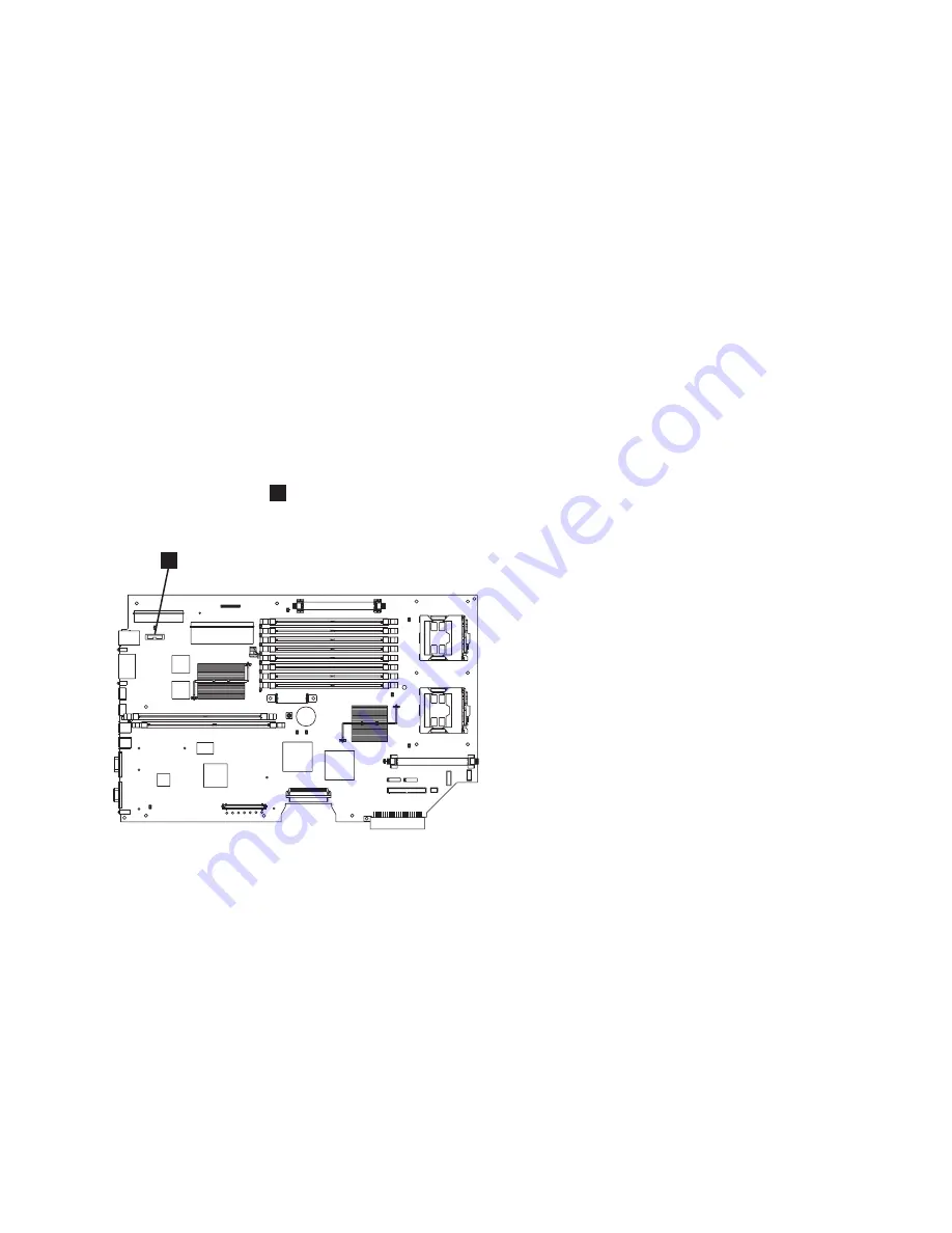
Locate the battery

1

on the system board. Figure 139 shows the location of the battery.

6.

Remove the battery:

a.

Use one finger to pull the retainer tab, which is shown in Figure 140 on page 134, that secures the
battery to its housing.

1

svc001

10

Figure 139. Location of the CMOS battery on the SAN Volume Controller 2145-8F2 or the SAN Volume Controller
2145-8F4

Chapter 2. Removing and replacing parts

133

Summary of Contents for SAN Volume Controller

Page 1: ...System Storage SAN Volume Controller Hardware Maintenance Guide Version 6 Release 1 GC27 2226 03...

Page 2: ......

Page 3: ...System Storage SAN Volume Controller Hardware Maintenance Guide Version 6 Release 1 GC27 2226 03...

Page 4: ...ironmental Notices and User Guide on the documentation CD This edition applies to the IBM System Storage SAN Volume Controller Version 6 1 0 and to all subsequent releases and modifications until othe...

Page 5: ...rt rails for a SAN Volume Controller 54 Installing the support rails for a SAN Volume Controller 58 Removing the top cover 68 Replacing the top cover 72 Removing the service controller 75 Replacing th...

Page 6: ...upport rails for a 2145 UPS 1U 280 Installing the support rails for the 2145 UPS 1U 281 Removing the power cable from the 2145 UPS 1U 283 Removing the 2145 UPS 1U battery 284 Replacing the 2145 UPS 1U...

Page 7: ...ed 33 27 The SAN Volume Controller 2145 8G4 with cable retention bracket type B attached 34 28 SAN Volume Controller 2145 CF8 cable retention brackets 35 29 Raising the SAN Volume Controller 2145 CF8...

Page 8: ...card 81 82 SAN Volume Controller 2145 8A4 service controller release button 82 83 SAN Volume Controller 2145 8G4 service controller release button 83 84 Removing the service controller from the SAN Vo...

Page 9: ...ry 131 137 Location of the SAN Volume Controller 2145 8G4 CMOS battery holder 132 138 SAN Volume Controller 2145 8G4 CMOS battery holder 132 139 Location of the CMOS battery on the SAN Volume Controll...

Page 10: ...peed SAS cable connected to the disk backplane in the SAN Volume Controller 2145 CF8 178 195 High speed SAS adapter assembly and high speed SAS cable in the SAN Volume Controller 2145 CF8 179 196 Boot...

Page 11: ...226 250 Location of the microprocessor and VRM sockets 227 251 Opening the SAN Volume Controller 2145 CF8 microprocessor bracket frame 229 252 Closing the SAN Volume Controller 2145 CF8 microprocesso...

Page 12: ...onnector 274 302 The 2145 UPS 1U internal battery connector with protective tape 275 303 Mounting screws for the 2145 UPS 1U 275 304 Installing the support rails for a 2145 UPS 1U into the rack 276 30...

Page 13: ...que for the SAN Volume Controller 2145 8G4 Rev 1 version 10 10 FRU part numbers that are unique for the SAN Volume Controller 2145 8G4 Rev 2 version 10 11 FRUs in the SAN Volume Controller 2145 8G4 pa...

Page 14: ...xii IBM SAN Volume Controller Hardware Maintenance Guide...

Page 15: ...om storage support 2145 click the current product documentation link and then click Multi language General safety When you service the SAN Volume Controller redundant ac power switch or the uninterrup...

Page 16: ...t If an electrical accident occurs you can then operate the switch or unplug the power cord quickly v Do not work alone under hazardous conditions or near equipment that has hazardous voltages v Disco...

Page 17: ...u correct the problem Before you start the safety inspection make sure that the power is off and that the power cord is disconnected Each device has required safety items installed to protect users an...

Page 18: ...es are in the correct operating condition 3 If SAN Volume Controller is not installed in a rack cabinet check for loose or broken feet 4 Check the power cord for damage 5 Check the external signal cab...

Page 19: ...f redundant ac power is used turn off any SAN Volume Controller that is being supplied from the redundant ac power switch and remove the power cable to this system from the redundant ac power switch 9...

Page 20: ...ous or lethal electrical shock Explosive hazards A bulging capacitor can cause serious injury Mechanical hazards Loose or missing items for example nuts and screws can cause serious injury Use caution...

Page 21: ...exposed printed circuitry v Do not leave the device where others can handle and possibly damage the device v While the device is still in its antistatic bag touch it to an unpainted metal part of the...

Page 22: ...xx IBM SAN Volume Controller Hardware Maintenance Guide...

Page 23: ...ly Summary of changes This document contains terminology maintenance and editorial changes Technical changes or additions to the text and illustrations are indicated by a vertical line to the left of...

Page 24: ...hardware and software SC23 8824 Read This First Installing the IBM System Storage Productivity Center This guide describes how to install the IBM System Storage Productivity Center hardware GI11 8938...

Page 25: ...harge You can also order publications The publications center displays prices in your local currency You can access the IBM Publications Center through the following Web site www ibm com e business li...

Page 26: ...xxiv IBM SAN Volume Controller Hardware Maintenance Guide...

Page 27: ...roller supports several different node types A label on the front of the node indicates the SAN Volume Controller node type hardware revision if appropriate and serial number SAN Volume Controller 214...

Page 28: ...ce procedures v Table 4 on page 5 lists the FRUs that are not referred to by any SAN Volume Controller 2145 CF8 service procedure but that might be replaced in some circumstances v SAN Volume Controll...

Page 29: ...l SFP transceivers replace the SFP transceivers on the FRU part with the SFP transceivers from the fibre channel adapter that is being replaced 5 39Y7201 2 Power supply unit Ac power supply 675 Watt 6...

Page 30: ...t SFP transceivers other than those shipped with the product are in use on the fibre channel host bus adapter It is a customer responsibility to obtain replacement parts for such SFP transceivers The...

Page 31: ...eature Description Part number Quantity Feature Code Long wave SFP transceiver FRU Long wave SFP transceiver that provides an auto negotiating 2 4 or 8 gigabits per second 10 kilometer km long wave op...

Page 32: ...olume Controller 2145 8A4 service procedures Use the assembly index number to locate and identify the parts that are shown in Figure 2 Table 6 FRUs that are exchanged within SAN Volume Controller 2145...

Page 33: ...es 7 39Y7289 1 Power supply 351 watt 8 39M4322 5 Fan 40 mm 10 41Y8247 1 Hard disk drive 3 5 in simple swap SATA This disk drive when ordered as a replacement will be a supported compatible drive of at...

Page 34: ...e Table 7 FRUs that are not exchanged within SAN Volume Controller 2145 8A4 service procedures Assembly index Part number Quantity Description 32P9107 1 Support rail kit 31P1171 1 Cable retention brac...

Page 35: ...des that are working in a cluster Table 8 Distinctive characteristics of the SAN Volume Controller 2145 8G4 versions Rev 1 version Rev 2 version There is one label on the front of the node and it does...

Page 36: ...unique for the SAN Volume Controller 2145 8G4 Rev 1 version Assembly index Part number Units Description 2 42C4228 2 Microprocessor 2 33 GHz with heat sink 3 39M5784 8 Memory 1 GB ECC DRR2 Table 10 F...

Page 37: ...ower back plane 23R2770 1 Fibre channel SFP transceiver 31P1063 1 Power cable assembly SAN Volume Controller to 2145 UPS 1U 39M5700 1 External fibre channel cable LC LC 5 0 m 16 4 ft 39M5701 1 Externa...

Page 38: ...e Controller 2145 8F4 are assembled Table 13 provides the part numbers and a brief description of the frame assembly parts that are labeled in Figure 4 The frame assembly comprises all the parts excep...

Page 39: ...rator information panel 11 40K8156 1 Fan holder with fan backplanes 13 40K8139 3 Fan 40 40 28 14 40K8140 4 Fan 40 40 56 73P2870 8 Memory 1 GB ECC DRR2 Table 14 Items not included in the SAN Volume Con...

Page 40: ...nnel cards These parts are listed in Table 16 on page 15 Table 15 SAN Volume Controller 2145 8F2 frame assembly Assembly index Part number Units Description 64P7934 1 Frame assembly 1 23K4219 1 Top co...

Page 41: ...n 40 40 28 16 33P2335 4 Fan 40 40 56 73P2870 8 Memory 1 GB ECC DRR2 Table 16 Items not included in the SAN Volume Controller 2145 8F2 frame assembly Assembly index Part number Units Description 2 64P7...

Page 42: ...r supply You must still use a uninterruptible power supply for each node Figure 6 shows the redundant ac power switch Table 17 lists the part numbers for the redundant ac power switch Table 17 Redunda...

Page 43: ...lied as part of the 2145 UPS 1U assembly 4 31P0709 1 Front panel 5 31P1060 1 2145 UPS 1U cable retention bracket kit 31P0711 1 Support rail kit contains rails nut clips and screws 39M5376 1 Input powe...

Page 44: ...nique Mauritania Mauritius Monaco Morocco Mozambique Netherlands New Caledonia Niger Norway Poland Portugal Romania Senegal Slovakia Spain Sudan Sweden Syria Togo Tunisia Turkey former USSR Vietnam fo...

Page 45: ...ck the correct node and click Manage to display all the volumes that are dependent on a node You can also use the node parameter with the svcinfo lsdependentvdisks CLI command to view dependent volume...

Page 46: ...You might be instructed to turn on the node and look at system board LEDs while the cover is off Follow these guidelines when you work inside a node that is turned on v Avoid wearing loose fitting cl...

Page 47: ...steps 1 Remove all power from the node as described in MAP 5350 in the IBM System Storage SAN Volume Controller 2145 Troubleshooting Guide 2 Disconnect all cables from the back of the SAN Volume Contr...

Page 48: ...on page 23 then slide the cable management arm tab out of the slot 4 on the outside of the slide rail b Pull the tab until it is free c Pull out the other cable management arm pin 1 then slide the cab...

Page 49: ...support arm is not shown in Figure 12 on page 24 Pull out the mounting bracket pin 1 and slide the mounting bracket 2 out of the left slide rail Pull the bracket from the slide rail until it is free s...

Page 50: ...ve the L shaped cable management stop bracket on the unattached end of the support arm Turn the bracket as shown by 1 in Figure 14 on page 25 to free it from the support arm Then lift the cable manage...

Page 51: ...r you replace the node in the rack The cable management arm is installed to pivot from the left side of the SAN Volume Controller 2145 CF8 rack when viewed from the rear of the rack To attach the cabl...

Page 52: ...ble support arm stop bracket as shown by 1 in Figure 18 to slide the bracket 2 into the slide rail 2 svc_bb1ka025 1 2 Figure 16 Rack rear Attaching the SAN Volume Controller 2145 CF8 cable management...

Page 53: ...snaps into place 5 Place the cable management arm on the support arm a Pull out the cable management arm pin as shown by 1 in Figure 20 on page 28 then slide the cable management arm tab 2 into the s...

Page 54: ...n perform some service procedures from the fully extended rail position without disconnecting the fibre channel cables and the Ethernet cables You can also perform some service procedures without turn...

Page 55: ...cable retention brackets You can remove the two SAN Volume Controller 2145 CF8 cable retention brackets when removing the power cords from the node DANGER Multiple power cords The product might be equ...

Page 56: ...ndent VDisks on the node you do not lose access to data if this node accidentally powers off 3 Pull back the cable management arm if you are working from the rear of the rack or slide the node out of...

Page 57: ...he cable 5 Remove the power cable Removing the SAN Volume Controller 2145 8G4 cable retention bracket The SAN Volume Controller 2145 8G4 uses one of two different cable retention brackets Depending on...

Page 58: ...s to the back of the SAN Volume Controller 2145 8G4 node It is connected with the screws that already hold the rear plate of the power supply in place Remove the cable retention bracket before you rem...

Page 59: ...lume Controller 2145 8G4 cable retention bracket option B Remove the cable retention bracket before you remove the SAN Volume Controller 2145 8G4 from the rack To remove the cable retention bracket pe...

Page 60: ...tion bracket Replace the cable retention bracket after you install SAN Volume Controller model 2145 8A4 2145 8G4 or 2145 8F4 into the rack Replacing the SAN Volume Controller 2145 CF8 cable retention...

Page 61: ...power cord by slipping the power cord into the notch on the rear of the bracket 4 Align the cable retention bracket on the power cord so that the bracket is to the left of the cord as shown by 2 in F...

Page 62: ...turns but do not fully remove the screw as shown in Figure 30 3 Slide the bracket jaw over the power cable 4 Slide the bracket down the cable until it is next to the power plug and slightly to the rig...

Page 63: ...roller 2145 8G4 uses one of two different cable retention brackets Depending on which bracket you have use the appropriate instructions to remove and replace the cable retention bracket v If your cabl...

Page 64: ...troller 2145 8G4 node It is connected with the screws that already hold the rear plate of the power supply in place Replace the SAN Volume Controller 2145 8G4 cable retention bracket after you replace...

Page 65: ...over the retention bracket and replace the lower screw so that it holds the power supply handle cable retention bracket and power supply rear plate in place Replacing the cable retention bracket optio...

Page 66: ...e is held by the slot on the end of the bracket Figure 36 provides a view of how to align the cable retention bracket with the cable 3 Position the cable retention bracket against the support rail and...

Page 67: ...e channel cables at any time Removing the SAN Volume Controller 2145 CF8 from a rack Use these instructions when you are prompted to remove a SAN Volume Controller 2145 CF8 from a rack DANGER Multiple...

Page 68: ...ectrical shock R001 part 1 of 2 DANGER v Do not install a unit in a rack where the internal rack ambient temperatures will exceed the manufacturer s recommended ambient temperature for all your rack m...

Page 69: ...the node from the front and the back and pull the node forward slightly and lift to remove the node from the back of the rails 3 Removing the SAN Volume Controller 2145 8A4 from a rack Use these inst...

Page 70: ...stall a unit in a rack where the internal rack ambient temperatures will exceed the manufacturer s recommended ambient temperature for all your rack mounted devices v Do not install a unit in a rack w...

Page 71: ...N Volume Controller is not already turned off see Turning off the SAN Volume Controller node in the IBM System Storage SAN Volume Controller 2145 Troubleshooting Guide Attention Do not touch the power...

Page 72: ...stall a unit in a rack where the internal rack ambient temperatures will exceed the manufacturer s recommended ambient temperature for all your rack mounted devices v Do not install a unit in a rack w...

Page 73: ...touch the power control switches on adjacent SAN Volume Controller nodes when you remove or install SAN Volume Controller nodes in a rack Touching these switches on adjacent SAN Volume Controller nod...

Page 74: ...rawers Do not pull out or install any drawer or feature if the rack stabilizer brackets are not attached to the rack Do not pull out more than one drawer at a time The rack might become unstable if yo...

Page 75: ...e rack cabinet v Rack mounted devices are not to be used as shelves or work spaces Do not place objects on top of rack mounted devices v Each rack cabinet might have more than one power cord Be sure t...

Page 76: ...become unstable or cause the drawer to fall out of the rack R001 part 2 of 2 Replacing the SAN Volume Controller 2145 CF8 in a rack Follow these instructions when you are prompted to replace the SAN...

Page 77: ...Turn on the node Replacing the SAN Volume Controller 2145 8A4 in a rack Follow these instructions when you are prompted to replace the SAN Volume Controller 2145 8A4 Attention Do not touch the power...

Page 78: ...Controller 2145 8G4 Attention Do not touch the power control switches on adjacent SAN Volume Controller nodes when you remove or install SAN Volume Controller nodes in a rack Touching these switches o...

Page 79: ...he node in the slides 4 Reconnect the fibre channel and Ethernet cables Ensure that you replace the fibre channel and Ethernet cables in the same ports from which they were removed Figure 43 The capti...

Page 80: ...5 8F4 or the SAN Volume Controller 2145 8F2 in the rack 1 Slide the SAN Volume Controller 2145 8F4 or the SAN Volume Controller 2145 8F2 node into the rack 2 Latch the two latches on the front of the...

Page 81: ...b Lift slightly then push back on the rail 3 4 Remove the side rails from the front of the rack and remove the rails a To remove the slide rails from the front of the rack push up the front tab 1 in...

Page 82: ...ving the support rails for the SAN Volume Controller 2145 8G4 This topic describes how to remove the SAN Volume Controller 2145 8G4 support rails Perform the following steps to remove the SAN Volume C...

Page 83: ...ng the support rails for the SAN Volume Controller 2145 8F4 or SAN Volume Controller 2145 8F2 This topic describes how to remove the SAN Volume Controller 2145 8F4 or SAN Volume Controller 2145 8F2 su...

Page 84: ...nstall the support rails use the hardware location chart of the customer and the Electronic Industries Alliance EIA positions on the rack to determine where in the rack that the SAN Volume Controller...

Page 85: ...rack a Pull the slide rail forward and insert the metal of the rack between the front latch and the pins as shown by 1 in Figure 54 on page 60 Insert the two pins into the two lower holes in the U on...

Page 86: ...a rack 1 Rear of rail 2 Shipping bracket 3 M6 screws 6 4 Rack mounting rails 5 Front of rail Notes v With some types of racks you might find it helpful to remove the rack doors and side panels to pro...

Page 87: ...rriers at the front and rear of each support rail are open The mechanism to open is similar at each end If a locking mechanism is closed as shown in Figure 56 for a front bracket open it To open the r...

Page 88: ...blue tab 3 away from the rail The pins spring into the closed position Ensure that the pins go fully through the holes in the mounting flange as shown in Figure 58 on page 63 c At the rear of the rack...

Page 89: ...the customer s hardware location chart and the Electronic Industries Alliance EIA positions on the rack to determine where in the rack that the SAN Volume Controller node is to be installed Perform th...

Page 90: ...rm this procedure for both rails 3 Insert the right slide rail 2 into the rear rack mounting flange as shown in Figure 60 with the rail pins 1 protruding through the flange 4 Extend the right slide ra...

Page 91: ...plete Installing the support rails for the SAN Volume Controller 2145 8F4 or the SAN Volume Controller 2145 8F2 You must install the support rails that hold the SAN Volume Controller 2145 8F4 or the S...

Page 92: ...tly push the latch lock 2 away from the rail as you move the latch lever 1 toward the far end of the rail Figure 64 The latch lock carrier assembly slides against the spring tension 1 Latch lever 2 La...

Page 93: ...racket 6 Place the front end of the left rail in the rack cabinet Align the top of the front bracket 1 Figure 66 with the required EIA marking that is on the rack 1 Front bracket 2 Rack mounting flang...

Page 94: ...g pins project through the holes that are in the rear flange and in the rear rail bracket Important Ensure that the locating pins are fully extended through the rear rail bracket 11 On the rear of eac...

Page 95: ...d and the data cables connected However do not run the node for longer than thirty minutes without the cover If you must take a longer time turn off the node as directed in MAP 5350 3 Pull back the ca...

Page 96: ...ving the SAN Volume Controller 2145 8G4 top cover This topic describes how to remove the SAN Volume Controller 2145 8G4 top cover Important Before you turn on the node replace the cover for proper coo...

Page 97: ...e node replace the cover for proper cooling and airflow Operating the node for extended periods of time more than 30 minutes with the cover removed might damage components Before you remove the cover...

Page 98: ...ontroller 2145 CF8 top cover This topic describes how to replace the SAN Volume Controller 2145 CF8 top cover Important Before you slide the cover forward make sure that all the tabs on both the front...

Page 99: ...difficult to remove the cover later 5 Slide the cover toward the front of the node as shown in Figure 72 1 Cover 2 Blue locking tab 6 Verify that the cover correctly engages all the inset tabs on the...

Page 100: ...be very difficult to remove the cover later To replace the top cover on the SAN Volume Controller 2145 8G4 complete the following steps 1 Position the internal cables so that they do not interfere wi...

Page 101: ...latch 4 Close the fan doors 5 Replace the node in the rack Removing the service controller You can remove the service controller from the SAN Volume Controller Removing the SAN Volume Controller 2145...

Page 102: ...ode in the rack is too high or too low to work comfortably you can remove the node from the rack Fast path You can perform this service procedure with the node in place 5 If you must remove the node f...

Page 103: ...CF8 8 Pull the service controller fully out of the frame If you are replacing a hot swap drive you can leave the service controller cable attached to the service controller You can suspend the service...

Page 104: ...s you to remove the cover and v Turn the node off v Disconnect the power cables v Disconnect or reconnect the USB service controller data cable Perform the following steps to remove or replace the ser...

Page 105: ...rack on page 40 6 7 Remove the service controller from the SAN Volume Controller 2145 CF8 as described in Removing the SAN Volume Controller 2145 CF8 service controller on page 75 8 Remove or replace...

Page 106: ...page 81 and slide it toward the USB riser card assembly 3 to the unlock position and remove the USB cable 1 from the connector Figure 80 USB service controller cable connected to the disk controller...

Page 107: ...f the service controller e Carefully install the service controller as described in Replacing the SAN Volume Controller 2145 CF8 service controller on page 85 Important Ensure that the USB cable is pu...

Page 108: ...arly label the service controller that you are removing and indicate that its WWNN is now a duplicate and that it must not be connected to a SAN before its WWNN is reset Removing the SAN Volume Contro...

Page 109: ...ou replace a service controller it is normal to change the worldwide node name WWNN of the new service controller to match the one that is being replaced In this case you will have two service control...

Page 110: ...eshooting Guide for more information 2 3 Open fan door A 1 in Figure 85 of the node 1 Fan door A 2 Fan door B 4 Lift the two blue levers on the rear of the cage assembly to release it from the frame 5...

Page 111: ...N is reset 7 Remove the retention clip 2 Make sure to save the retention clip for when you reinstall the node Replacing the service controller You can replace the SAN Volume Controller service control...

Page 112: ...the rack replace the node in the rack as described in Replacing the SAN Volume Controller in a rack on page 48 5 If you removed any fibre channel or Ethernet cables use the labels you placed on each c...

Page 113: ...the WWNN for the node is not correct restore the WWNN by performing the following steps a Determine the WWNN for the node by examining the vital product data VPD of the node or the zoning that is defi...

Page 114: ...et See Replacing the cable retention bracket on page 34 Note If you replaced the service controller as part of concurrent maintenance you must rewrite the WWNN on the new service controller If you do...

Page 115: ...ooting Guide to determine how to solve this problem or contact the IBM support center Replacing the SAN Volume Controller 2145 8G4 service controller Use the following information to replace the SAN V...

Page 116: ...ighlighted number to match the number from the VPD or from customer zoning Use the up and down buttons to increase or decrease the numbers The numbers wrap F to 0 or 0 to F Use the left and right butt...

Page 117: ...have to re zone the fibre channel switches if the switch zoning uses WWPN You must restart the host systems before they are able to access disks through this node 5 If you replaced the service control...

Page 118: ...nt panel this indicates that the node is ready to be added to the cluster If Cluster does not display see MAP 5000 in the IBM System Storage SAN Volume Controller 2145 Troubleshooting Guide to determi...

Page 119: ...g you cannot access any of the disks in that I O group 2 Turn off the node while ensuring that its data is mirrored and synchronized See MAP 5350 in the IBM System Storage SAN Volume Controller 2145 T...

Page 120: ...2145 UPS 1U cable retention bracket 10 For the SAN Volume Controller model 2145 CF8 route the power cords on the cable management arm secure the power cords with cable ties or hook and loop fasteners...

Page 121: ...dules are numbered 1 through 4 as shown in Figure 96 on page 96 1 1 2 3 4 5 6 7 8 9 10 11 12 13 14 15 16 2 3 5 6 7 8 svc_nn1em002 Figure 95 Locating the SAN Volume Controller 2145 CF8 memory modules C...

Page 122: ...ugh 8 which are shown in Figure 97 The second version of this node Rev 2 uses four 2 GB memory modules in slots 1 3 5 and 7 Figure 96 Locating the SAN Volume Controller 2145 8A4 memory modules 1 5 6 7...

Page 123: ...from the rack and place it on a flat static protective surface See Removing the SAN Volume Controller from a rack on page 40 3 Remove the top cover See Removing the top cover on page 68 Attention If...

Page 124: ...the second version Rev 2 has four 2 GB memory modules The label on the Rev 1 node does not include a version number An additional label on the front of the Rev 2 node includes the version number Ensu...

Page 125: ...e configuration program and then restart the node f If the error displays again remove and replace the memory module again to ensure that it is seated correctly If that does not resolve the error the...

Page 126: ...ume Controller 2145 Troubleshooting Guide for more information 3 Remove the cable retention bracket and disconnect the power cable from the node See Removing the cable retention bracket on page 29 4 R...

Page 127: ...er 2145 4F2 disk drive Attention v Handle the disk drive with care and keep it away from strong magnetic fields v The disk drive is electrostatic discharge ESD sensitive Take precautions to avoid dama...

Page 128: ...ew disk drive Attach the rails to the disk drive as shown in Figure 104 10 Keep the disk drive that you removed if it has any jumpers installed because you will need to set the same jumpers on the rep...

Page 129: ...rack 4 Optional If you must remove the node from the rack to work on it perform the following procedure to remove all cables and remove the node from the rack a Pull back the cable management arm if...

Page 130: ...ou are instructed to return the drive assembly follow all packaging instructions and use any packaging materials for shipping that are supplied to you IDs for SAN Volume Controller 2145 CF8 disk drive...

Page 131: ...steps 1 Make sure that the cover is in place and fully closed Attention To avoid damage to the hard disk drive connectors make sure that the cover is in place and fully closed whenever you install or...

Page 132: ...2145 Troubleshooting Guide for more information 2 Remove the SAN Volume Controller 2145 8F4 cable retention bracket 3 To make sure that you can replace all cables in the same ports from which they we...

Page 133: ...d follow those instructions in addition to the instructions in this topic v Make sure that you have all the cables and other equipment that are specified in the documentation that comes with the drive...

Page 134: ...escribed in Replacing the SAN Volume Controller in a rack on page 48 10 Make sure that all cables adapters and other components are installed and seated correctly and that you have not left loose tool...

Page 135: ...Controller 2145 8A4 and the SAN Volume Controller 2145 8G4 nodes You can replace the SATA serial advanced technology attachment disk drive after you remove the existing disk drive To replace the SAN V...

Page 136: ...5 8F4 or SAN Volume Controller 2145 8F2 SATA disk drive This topic describes how to replace the SATA serial advanced technology attachment disk drive for the SAN Volume Controller 2145 8F2 and the SAN...

Page 137: ...in addition to the one required boot drive that ships with the node You do not have to turn off the node to perform this service action You can leave the node turned on the power cords connected and t...

Page 138: ...over is in place and fully closed Attention To avoid damage to the disk drive connectors make sure that the node cover is in place and fully closed whenever you remove or replace a disk drive 5 If the...

Page 139: ...Replacing a SAN Volume Controller 2145 CF8 solid state drive SSD 10 If you are instructed to return the drive assembly follow all packaging instructions and use any packaging materials for shipping t...

Page 140: ...rive SSD 2 Drive handle 3 Drive bay blank electromagnetic compatibility EMC filler assembly c Gently push the drive assembly into the bay until the drive stops d Rotate the tray handle to the closed l...

Page 141: ...you to remove the cover and v Turn the node off v Disconnect the power cables v Disconnect the internal SAS data cables To remove the SAN Volume Controller 2145 CF8 disk drive backplane complete the...

Page 142: ...moving the disk drive on page 99 9 10 Remove fans 4 5 and 6 as described in Removing the SAN Volume Controller 2145 CF8 fans on page 209 11 Disconnect all cables from the disk drive backplane Note You...

Page 143: ...Safety and environmental notices on page xiii 2 Turn off the node while ensuring that its data is mirrored and synchronized See MAP 5350 in the IBM System Storage SAN Volume Controller 2145 Troublesh...

Page 144: ...node Disconnect power cable connectors P2 1 and P3 2 shown in Figure 121 on page 119 and remove the back plate Figure 119 SAN Volume Controller 2145 8A4 SATA cable connectors svc00485 1 Figure 120 Ai...

Page 145: ...nformation 3 Remove the cable retention bracket and disconnect the power cable from the node See Removing the cable retention bracket on page 29 4 Remove the node from the rack and place it on a flat...

Page 146: ...onnect the power cable and remove the back plate 1 Locking tab 2 Mounting channel Figure 122 The SAN Volume Controller 2145 8G4 disk drive backplane connectors 1 svc00306 2 2 Figure 123 The SAN Volume...

Page 147: ...ign the tabs on the disk drive backplane with the slots on the backplane bracket 2 Insert the disk drive backplane tabs into slots on the backplane bracket and push the disk drive backplane down until...

Page 148: ...ed into the middle of the backplane to support drive bays 0 1 2 and 3 4 Reconnect the boot disk SAS cable to the SAS disk controller The boot drive cable and the high speed SAS adapter cable are shown...

Page 149: ...e rack replace the node in the rack as described in Replacing the SAN Volume Controller in a rack on page 48 10 If you removed any fibre channel or Ethernet cables use the labels you placed on each ca...

Page 150: ...The air deflector also functions as the back plate latch In this procedure you must lift the air deflector to access some of the cables 2 Connect power cable connectors P2 1 and P3 2 to the replaceme...

Page 151: ...ess it down firmly 6 Reconnect the SATA cables to the system board When you look from the front SATA 0 is the drive number for the left bay and SATA 2 is the drive number for the right bay Note Make s...

Page 152: ...and Ethernet cables in the same ports from which they were removed 12 Turn on the node Replacing the SAN Volume Controller 2145 8G4 disk drive backplane To replace the SAN Volume Controller 2145 8G4 d...

Page 153: ...to the rear system board connector as shown in Figure 132 5 Install the hard disk drive See Replacing the disk drive on page 107 6 7 Replace the top cover See Replacing the top cover on page 72 8 Plac...

Page 154: ...s instructed by local regulations In the United States IBM has a process for the collection of this battery For information call 1 800 426 4333 Have the IBM part number for the battery unit available...

Page 155: ...n page 40 6 7 Locate the battery 1 on the system board Figure 133 shows the location of the battery 8 Remove the CMOS battery as shown in Figure 134 a Use a fingernail to press the top of the battery...

Page 156: ...d the safety precautions in Safety and environmental notices on page xiii 2 Turn off the node while ensuring that its data is mirrored and synchronized See MAP 5350 in the IBM System Storage SAN Volum...

Page 157: ...local regulations In the United States IBM has a process for the collection of this battery For information call 1 800 426 4333 Have the IBM part number for the battery unit available when you call C...

Page 158: ...et Removing the SAN Volume Controller 2145 8F4 or SAN Volume Controller 2145 8F2 CMOS battery This topic describes how to remove the SAN Volume Controller 2145 8F4 and SAN Volume Controller 2145 8F2 C...

Page 159: ...lation instructions supplied with the battery 2 Turn off the node while ensuring that its data is mirrored and synchronized See MAP 5350 in the IBM System Storage SAN Volume Controller 2145 Troublesho...

Page 160: ...product might be equipped with multiple power cords To remove all hazardous voltages disconnect all power cords CAUTION The battery contains lithium To avoid possible explosion do not burn or charge...

Page 161: ...the fibre channel and Ethernet cables make sure that each cable is reconnected to the same port from which it was removed 5 Replace the top cover See Replacing the top cover on page 72 6 If you remov...

Page 162: ...at to more than 100 C 212 F v Repair or disassemble Exchange only with the IBM approved part Recycle or discard the battery as instructed by local regulations In the United States IBM has a process fo...

Page 163: ...placing the SAN Volume Controller in a rack on page 48 7 Reconnect the external cables and then reconnect the power cords and the node Note You must wait approximately 20 seconds after you connect pow...

Page 164: ...in parentheses at the end of each notice such as C003 for example to find the matching translated notice in IBM Systems Safety Notices Perform the following steps to replace the SAN Volume Controller...

Page 165: ...o not burn or charge the battery Do not v Throw or immerse into water v Heat to more than 100 C 212 F v Repair or disassemble Exchange only with the IBM approved part Recycle or discard the battery as...

Page 166: ...See Replacing the SAN Volume Controller in a rack on page 48 Removing the power supply You must remove the SAN Volume Controller power supply if you intend to replace it Use the reference numbers in...

Page 167: ...Follow the procedure in MAP 5350 in the IBM System Storage SAN Volume Controller 2145 Troubleshooting Guide to verify that the node data is mirrored and synchronized and that there are no dependent v...

Page 168: ...ces on page xix To remove the power supply perform the following steps Notes v The air deflector also functions as the back plate latch In this procedure you must lift the air deflector to access some...

Page 169: ...k plate far enough to disconnect the two power cables from it See Removing the disk drive backplane on page 115 7 Disconnect the power supply cables from the 24 PIN POWER connector 1 and the POWER con...

Page 170: ...3 shown in Figure 154 on page 145 that holds the power supply to the rear of the chassis svc00483 Figure 152 Power P5 connector on the SAN Volume Controller 2145 8A4 power supply svc00486 1 Figure 153...

Page 171: ...steps to remove the power supply 1 Turn off the node while ensuring that its data is mirrored and synchronized See MAP 5350 in the IBM System Storage SAN Volume Controller 2145 Troubleshooting Guide f...

Page 172: ...Turn off the 2145 UPS 1U that is supplying this node 3 Remove the SAN Volume Controller 2145 8F4 cable retention bracket 4 From the rear of the node as shown in Figure 156 push the orange release lev...

Page 173: ...oven methods avoids risking an abrupt power failure on the node which avoids the possible corruption of data This procedure assumes that you have turned off the node using MAP 5350 or that if you did...

Page 174: ...rackets on page 34 4 If necessary turn on the node 5 To the left of the power cord connector on each power supply verify that the ac power LED as shown by 1 in Figure 158 on page 149 and the dc power...

Page 175: ...following steps 1 Place the new power supply into the bay 2 Tighten the captive thumbscrew that secures the rear of the power supply to the chassis bottom 3 Replace the screw that holds the power supp...

Page 176: ...e labeled P6 2 to the position marked POWER 6 Route the power supply cable with the P5 connector to the CD DVD interface card and secure it under the retention clip 1 as shown in Figure 161 on page 15...

Page 177: ...stop and display boot code Failed 181 This is expected because the uninterruptible power supply is not connected Proceed to the next step v If the node does not start disconnect the ac power cord and...

Page 178: ...icks in place 1 Power supply 2 Power supply release tab 3 Power supply handle 2 Connect the power cord to the power cord connector on the power supply being sure to route the cord through the cable re...

Page 179: ...Volume Controller 2145 8F2 power supply perform the following steps 1 Install the power supply in the empty power supply bay a Rotate the handle 1 down on the rear of the power supply to the open posi...

Page 180: ...e Controller 2145 8G4 power backplane Take precautions to avoid damage from static electricity Wear an anti static wrist strap and use a static protected mat or surface For more information see Handli...

Page 181: ...ng steps to remove the power backplane 1 Turn off the node while ensuring that its data is mirrored and synchronized See MAP 5350 in the IBM System Storage SAN Volume Controller 2145 Troubleshooting G...

Page 182: ...information see Handling static sensitive devices on page xix Perform the following steps to replace the power backplane 1 Align the keyhole slots in the power supply backplane with the mounting pins...

Page 183: ...45 8F4 or SAN Volume Controller 2145 8F2 power backplane might have to be replaced Take precautions to avoid damage from static electricity Wear an anti static wrist strap and use a static protected m...

Page 184: ...the actions that you must take or have already taken to determine how the node can be added back to the cluster v If you are replacing the node because the new service controller did not fix the origi...

Page 185: ...WWNN of the node b Rezone the switch to allow at least one port of the replaced node to connect to at least one port of an existing node c Perform a node rescue d Set the WWNN of the replacement node...

Page 186: ...move the fibre channel cable by pressing the release tab and pulling the cable out Be careful to exert pressure only on the connector and do not pull on the fibre channel cables 3 Remove the SFP trans...

Page 187: ...p and use a static protected mat or surface For more information see Handling static sensitive devices on page xix Removing the SAN Volume Controller 2145 CF8 fibre channel adapter assembly To remove...

Page 188: ...lace all cables in the same ports from which they were removed label the port position of each fibre channel and Ethernet cable then remove all cables from the back of the node 6 Optional Remove the n...

Page 189: ...present attaches to the slot 2 connector on the left side of the system board when looking from the back If there is no high speed SAS adapter riser card assembly a riser card adapter is present in s...

Page 190: ...static protective surface See Removing the SAN Volume Controller from a rack on page 40 Remove the node from the rack and place it on a flat static protective surface See Removing the SAN Volume Cont...

Page 191: ...remove the main power cable retention bracket and remove the power cable from the rear of the node 3 After writing down their locations remove all other cables from the node 4 Remove the node from th...

Page 192: ...l HBA identified 1 PCI slot 2 contains a 4 port fibre channel HBA Perform the following steps to remove a fibre channel adapter assembly 1 Turn off the node while ensuring that its data is mirrored an...

Page 193: ...s of the slot 2 riser card 2 in Figure 182 on page 168 by pushing the clips down and away from the riser card until the clips are no longer attached to the riser card Note Insert your finger into the...

Page 194: ...duct might be equipped with multiple power cords To remove all hazardous voltages disconnect all power cords 1 Remove all small form factor pluggable SFP transceivers as described in Removing and repl...

Page 195: ...adapters and other components are installed and seated correctly and that you have not left loose tools or parts inside the node Make sure that all internal cables are correctly routed If you disconne...

Page 196: ...e guides on the rear of the node and with the riser card connectors on the system board Press down on the assembly and make sure that the riser card assembly is fully seated in the riser card connecto...

Page 197: ...pter assemblies are electrostatic discharge sensitive Take precautions to avoid damage from static electricity Wear an anti static wrist strap and use a static protected mat or surface For more inform...

Page 198: ...ous voltages disconnect all power cords This service action requires you to remove the cover and v Turn the node off v Disconnect the power cables v Disconnect the data cables To remove the SAN Volume...

Page 199: ...the high speed SAS adapter riser card assembly on a flat static protective surface 13 If you are instructed to return the high speed SAS adapter riser card assembly follow all packaging instructions...

Page 200: ...r on the low profile adapter 1 with the connector 3 on the riser card assembly 4 Make sure that the adapter snaps into the riser card securely Press the riser card edge connector firmly into the syste...

Page 201: ...lume Controller 2145 CF8 high speed SAS adapter cable perform the following steps 1 Read the safety information to which Preparing to remove and replace parts on page 20 refers 2 Follow the procedure...

Page 202: ...192 1 High speed SAS cable plugged into the high speed SAS adapter assembly 2 High speed SAS adapter assembly 9 Disconnect the high speed SAS cable from the high speed SAS adapter 10 Remove the cable...

Page 203: ...khead clip if necessary before removing the high speed SAS adapter cable from the clip 11 Disconnect the high speed SAS cable from the SAS connector in the center of the back of the disk backplane as...

Page 204: ...2145 CF8 Replacing the SAN Volume Controller 2145 CF8 high speed SAS cable You can replace the SAN Volume Controller 2145 CF8 high speed SAS cable Perform the following steps to replace the SAN Volume...

Page 205: ...dapter assembly on page 173 4 Disconnect the boot disk SAS cable from the disk controller and move it out of the blue bulkhead clip 5 Route the cable from the high speed SAS adapter through the blue b...

Page 206: ...rive bays 0 1 2 and 3 7 Reroute the boot disk SAS cable through the blue bulkhead clip and reconnect the cable to the disk controller The high speed SAS cable is shown in Figure 197 on page 181 1 2 Fi...

Page 207: ...r 2145 CF8 disk controller and USB riser card assembly DANGER Multiple power cords The product might be equipped with multiple power cords To remove all hazardous voltages disconnect all power cords T...

Page 208: ...Ethernet cable then remove all cables from the back of the node b Remove the node from the rack and place it on a flat static protective surface See Removing the SAN Volume Controller from a rack on p...

Page 209: ...ler and USB riser card assembly Take precautions to avoid damage from static electricity Wear an anti static wrist strap and use a static protected mat or surface For more information see Handling sta...

Page 210: ...htly and insert the end of the disk controller in the slot on the retention bracket as shown in the following illustration 1 Disk controller front retention bracket 2 Disk controller and USB riser car...

Page 211: ...the USB riser card 2 Service controller cable 9 Connect the SAS boot drive cable the cable to drive bays 4 and 5 to the connector on the disk controller that is closer to the power supplies 3 1 2 Fig...

Page 212: ...plugged into the disk drive backplane to support drive bay 4 2 High speed SAS adapter cable that is plugged into the middle of the backplane to support drive bays 0 1 2 and 3 Figure 204 on page 187 sh...

Page 213: ...rn on the node Removing the PCI express riser card assembly Use these instructions when you are prompted to remove the SAN Volume Controller PCI express riser card assembly Removing the SAN Volume Con...

Page 214: ...170 Removing the operator information panel assembly You might be prompted to remove the SAN Volume Controller operator information panel Take precautions to avoid damage from static electricity Wear...

Page 215: ...rator information panel assembly disconnect the cable 7 Use an object to push down on the release tab 2 in Figure 205 Hold down the release tab and push the blue push point on the rear of the panel to...

Page 216: ...G4 due to required maintenance Make careful note of the layout of the cables as you go through this procedure as they will need replacing in the same position when you replace the operator information...

Page 217: ...g it slightly and then removing the cable from it 1 Screw 2 Interposer card 3 Dummy CD DVD drive 5 Remove fan 3 as shown in Figure 209 on page 192 Figure 207 SAN Volume Controller 2145 8G4 dummy CD DV...

Page 218: ...the air baffle 2 in Figure 210 on page 193 AIR FL OW AIR FL OW AIR FL OW AIR FL OW AIR FL OW svc00277 AIR FLOW AIR FL OW 1 2 Figure 209 SAN Volume Controller 2145 8G4 fan 3 192 IBM SAN Volume Controll...

Page 219: ...m the system board There is no need to completely remove these cables Unplugging them makes it easier to maneuver the light path ribbon cable 4 In Figure 211 on page 194 the front of the node is at th...

Page 220: ...letely unthread the cable removing it from the three retaining brackets Also release it from any tape holding it in place The cable should be free to move forward with the operator information panel 9...

Page 221: ...AP 5350 in the IBM System Storage SAN Volume Controller 2145 Troubleshooting Guide for more information 2 Remove the SAN Volume Controller 2145 8F4 cable retention bracket 3 To make sure that you can...

Page 222: ...wo cables from the rear of the assembly 3 in Figure 215 Replacing the operator information panel assembly You might be prompted to replace the SAN Volume Controller operator information panel assembly...

Page 223: ...ide v The power cables are disconnected v The top cover is removed Perform the following steps to replace the operator information panel 1 Read the safety information to which Preparing to remove and...

Page 224: ...net cables in the same ports from which they were removed 7 If you removed the power cords replace the power cords and the cable retention brackets as described in Replacing the cable retention bracke...

Page 225: ...n the screws 3 to secure the operator information panel onto the top of the CD DVD bay housing 4 Replace the top cover See Replacing the top cover on page 72 5 Place the node in the rack See Replacing...

Page 226: ...in place 4 Thread the light path assembly ribbon cable 4 back to the system board Reconnect the cable to the system board socket 11 In Figure 221 the front of the node is shown at the bottom of the i...

Page 227: ...cable 9 to the system board 6 Replace the air baffle 2 It is easier to do this if you remove fan 2 Ensure that all the cables are routed correctly as shown in Figure 222 and not obstructing the fan do...

Page 228: ...de with the screw that you removed 9 Slide the dummy CD DVD drive 2 back into its enclosure AIR FL OW AIR FL OW AIR FL OW AIR FL OW AIR FL OW svc00277 AIR FLOW AIR FL OW 1 2 Figure 223 SAN Volume Cont...

Page 229: ...assembly 1 See Figure 225 1 Cables 2 Operator information panel assembly cover 2 Replace the assembly cover 2 onto the operator information panel assembly 3 Slide the assembly into the node until it i...

Page 230: ...ide v The power cables are disconnected v The top cover is removed Perform the following steps to remove the operator information panel cable 1 Read the safety information to which Preparing to remove...

Page 231: ...ect the power cable To make sure that you can replace all cables in the same ports from which they were removed record the position of all fibre channel and Ethernet cables then remove all external ca...

Page 232: ...the cable assembly 11 Carefully extract the cable assembly from the node To do this you must displace other cables particularly the optical drive cables power supply cables and the SATA cables Minimiz...

Page 233: ...read the new cable from the operator information panel to the connector above the Video USB cable connector on the right side of the node as shown in Figure 229 The following illustration shows the ca...

Page 234: ...4 operator information panel cable Use these instructions when you are prompted to replace the operator information panel cable for the SAN Volume Controller 2145 8A4 Perform the following steps to re...

Page 235: ...on the operator information panel board 5 If the back plate was removed replace the back plate disk drive and service controller See Removing the disk drive backplane on page 115 6 Rotate the air def...

Page 236: ...ed and synchronized and that there are no dependent volumes before turning off the node Important If you decide to hot swap the fan use MAP 5350 to make all of the necessary checks that ensure that th...

Page 237: ...sensitive devices on page xix Perform the following steps to remove a failed fan 1 Turn off the node while ensuring that its data is mirrored and synchronized See MAP 5350 in the IBM System Storage S...

Page 238: ...see Handling static sensitive devices on page xix Perform the following steps to remove a failed fan 1 Turn off the node while ensuring that its data is mirrored and synchronized See MAP 5350 in the I...

Page 239: ...s before you remove the SAN Volume Controller 2145 8F4 or SAN Volume Controller 2145 8F2 fans Perform the following steps to remove a failed fan 1 Turn off the node while ensuring that its data is mir...

Page 240: ...he orange tab on the side of the failing fan 6 Lift the fan out of the node Replacing the fans You might have to replace one or more SAN Volume Controller fans if they fail 1 2 3 svc00087 Figure 236 S...

Page 241: ...the IBM System Storage SAN Volume Controller 2145 Troubleshooting Guide to verify that the node data is mirrored and synchronized and that there are no dependent volumes before turning off the node Im...

Page 242: ...nside the node Make sure that all internal cables are correctly routed If you disconnected the fibre channel and Ethernet cables make sure that each cable is reconnected to the same port from which it...

Page 243: ...re information see Handling static sensitive devices on page xix Perform the following steps to replace a failed fan 1 Position the replacement fan shown in Figure 241 on page 218 so that the airflow...

Page 244: ...t each of the soft blue tabs on the fan is fully seated in its slot in the fan bracket d Reconnect the fan cable to the system board routing the cable in the same way as it was originally 3 Connect th...

Page 245: ...ollowing are true v The failed fan is removed v The node power is turned off v The node is removed from the rack Perform the following steps to replace a failed fan 1 Orient the new fan in the same po...

Page 246: ...backplanes The fan holder with fan backplanes field replaceable unit FRU is supplied as a kit of parts Replace only the failed assembly and discard any unused part Perform the following steps to remo...

Page 247: ...e off v Disconnect the power cables v Disconnect the data cables Attention v Do not permit the thermal grease on the microprocessor and heat sink to come in contact with anything Contact with any surf...

Page 248: ...in Figure 244 and the microprocessor 1 1 Microprocessor 2 Heat sink release lever 3 Heat sink 4 Lock tab 5 Retainer bracket 9 Push the heat sink release lever 1 down and away from the processor then l...

Page 249: ...er alcohol wipes and thermal grease separately if you do not already have them to correctly perform this task To remove the microprocessor complete the following steps 1 Turn off the node while ensuri...

Page 250: ...ure 246 that is closer to the middle of the node slide it toward the middle of the node slightly and lift the entire assembly out of the node 8 Open the microprocessor release latch to the fully open...

Page 251: ...you must have alcohol wipes and thermal grease available If you do not already have them order these separately Attention v Do not allow the thermal grease on the microprocessor and heat sink to come...

Page 252: ...loosened remove the heat sink 1 Heat sink 2 Heat sink installation label 3 Microprocessor 4 Alignment indicator 4 Open the microprocessor release lever 1 in Figure 249 to the fully open position 1 Mi...

Page 253: ...e ports from which they were removed record the position of all fibre channel and Ethernet cables then remove all cables from the back of the node 3 Remove the node from the rack and place it on a fla...

Page 254: ...is based on the following assumptions v You are a trained IBM service technician v You removed all power from the node v You removed the node from the rack v You removed the top cover of the node v Yo...

Page 255: ...dle the microprocessor carefully Dropping the microprocessor during installation or removal can damage the contacts v Do not use excessive force when you press the microprocessor into the socket v Ver...

Page 256: ...eat sink on a clean work surface b Remove the cleaning pad from its package and unfold it completely c Use the cleaning pad to wipe the thermal grease from the bottom of the heat sink Note Make sure t...

Page 257: ...nternal cables are correctly routed If you disconnected the fibre channel and Ethernet cables make sure that each cable is reconnected to the same port from which it was removed 13 Replace the top cov...

Page 258: ...and release latch 4 shown in Figure 256 on page 233 are both fully open Attention v The microprocessor contacts are fragile handle the microprocessor very carefully Do not touch the microprocessor co...

Page 259: ...work surface b Remove the cleaning pad from its package and unfold it completely c Use the cleaning pad to wipe the thermal grease from the bottom of the heat exchanger Make sure that all of the ther...

Page 260: ...gnment pins 1 shown in Figure 258 protrude through the alignment hole the opening in the side of the heat exchanger bracket and that the flange of the heat sink rests under the lip of the heat exchang...

Page 261: ...order them before you begin to replace the part The documented steps to replace the SAN Volume Controller 2145 8G4 microprocessor assume that you v Removed all power from the node v Removed the node f...

Page 262: ...0 Tighten the captive screws to secure the heat sink to the system board Alternate among the screws on either side of the heat sink until they are snug and then alternate again until they are tight ma...

Page 263: ...F4 or SAN Volume Controller 2145 8F2 microprocessor assume that you v Removed all power from the node v Removed the node from the rack v Removed the top cover of the node v Removed the microprocessor...

Page 264: ...that the thermal grease might have formed a strong bond between the heat sink and the microprocessor Do not force the heat sink and microprocessor apart doing so causes damage to the microprocessor p...

Page 265: ...irrored and synchronized See MAP 5350 in the IBM System Storage SAN Volume Controller 2145 Troubleshooting Guide for more information 2 Remove the SAN Volume Controller 2145 8F4 cable retention bracke...

Page 266: ...ages disconnect all power cords You must remove and replace the microprocessor when you replace the system board Ensure that you have alcohol wipes and thermal grease available to correctly perform th...

Page 267: ...er assembly on page 172 10 Remove the disk controller and USB riser card assembly as described in Removing the SAN Volume Controller 2145 CF8 disk controller and USB riser card assembly on page 181 11...

Page 268: ...se available to correctly perform this task Before you proceed with the system board removal ensure that you do the following v Identify and label all the cables that are attached to the SAN Volume Co...

Page 269: ...ge SAN Volume Controller 2145 Troubleshooting Guide 3 Remove the cable retention bracket and disconnect the power cable from the node See Removing the cable retention bracket on page 29 4 Remove the n...

Page 270: ...Fan 3 connector 12 Fan 2 connector 13 Fan 1 connector 14 IDE connector 8 Disconnect and remove both SATA disk cables from sockets SATA 0 and SATA from the system board as shown in Figure 266 9 Remove...

Page 271: ...e 268 12 Remove the five fan connectors along the front edge of the system board Figure 269 on page 246 shows three of the fan connectors 1 2 svc00482 Figure 267 SAN Volume Controller 2145 8A4 power s...

Page 272: ...an the heat sink now 15 Remove the microprocessor See Removing the microprocessor on page 221 16 Notice the orientation of the microprocessor retention module and then remove the four screws 1 in Figu...

Page 273: ...essor and four 2 GB memory modules Before you proceed with the system board removal ensure that you do the following v Identify and label all the cables that are attached to the SAN Volume Controller...

Page 274: ...r 2145 Troubleshooting Guide for more information 2 Remove the node from the rack and place it on a flat static protective surface See Removing the SAN Volume Controller from a rack on page 40 3 4 Rem...

Page 275: ...de the left air baffle 5 Then remove the left air baffle by pulling up gently svc00377 3 4 2 1 5 Figure 271 Connectors on the SAN Volume Controller 2145 8G4 system board svc00379 Figure 272 Left air b...

Page 276: ...d then pulling up e The uninterruptible power supply cable connector 4 f The video cable connector 3 10 Remove the remaining cables from the system board a The CD RW ribbon cable connector 1 by gently...

Page 277: ...clip from the system board Finally lift the baffle free 12 Carefully remove all the memory modules and set them aside on the static protected surface See Removing the memory modules DIMM on page 94 s...

Page 278: ...en the microprocessor release lever and then open the bracket frame b Carefully remove the microprocessor from the socket Be careful to touch only the edges of the microprocessor c Set the microproces...

Page 279: ...of the node so that the I O ports are free of the chassis 21 Lift up the left side of the system board 22 Lift up the rest of the system board and carefully remove it from the node being careful not t...

Page 280: ...eed a power cable so that you can turn on the node while it is out of the rack if necessary You must remove and replace the microprocessor when you replace the system board Ensure that you have alcoho...

Page 281: ...all of the cables that were removed previously 4 Reinstall the hot swap fans as described in Replacing the SAN Volume Controller 2145 CF8 fans on page 215 5 Reinstall the microprocessor and heat sink...

Page 282: ...he front panel display to remain stable for at least five minutes before taking any further action v If the repair has been successful and if the node was able to save its state data before shutting d...

Page 283: ...en the serial number is 13 FEDCB and the node name is ZYXW3 you would issue the following command svctask writesernum sernum 13FEDCB ZYXW3 Note The node will restart as soon as the serial number has b...

Page 284: ...and P6 10 Replace the riser card and fibre channel adapter and place them on a static protective surface for reinstallation See Replacing the fibre channel adapter assembly on page 168 11 Replace the...

Page 285: ...node error 578 Follow the procedures in Deleting a node from a cluster in the IBM System Storage SAN Volume Controller 2145 Troubleshooting Guide to delete the node from the cluster and then add it ba...

Page 286: ...odules Perform the following steps to install the system board 1 Lower the right side into place with the system board positioned slightly towards the front of the box Lower the left edge of the syste...

Page 287: ...back in to connect to it See Replacing the power backplane on page 156 5 Install one of the microprocessors while carefully checking the orientation and remembering to close the release lever which is...

Page 288: ...age 263 a Apply thermal grease to the top of the microprocessor Apply nine dots of thermal grease in three rows of three dots each with the outer rows approximately 5 mm from the edge of the microproc...

Page 289: ...for the second microprocessor and heat sink If this is a Rev 2 node continue with the next step 8 Replace either eight memory modules for the Rev 1 node or four memory modules for the Rev 2 node See...

Page 290: ...and the CD RW ribbon cable connector as shown in Figure 290 on page 265 a Replace the video cable connector and the USB cable connector b Replace the cable connectors for fans 6 5 4 and 3 svc00381 Fi...

Page 291: ...r 7 Fan 5 connector 8 Fan 6 connector 11 Replace the left air baffle which is shown in Figure 291 on page 266 You must position the CD RW cable within the baffle svc00378 1 3 4 5 6 7 8 2 Figure 290 Co...

Page 292: ...in Figure 292 1 Right disk signal cable connector svc00379 Figure 291 Left air baffle on the SAN Volume Controller 2145 8G4 svc00377 3 4 2 1 5 Figure 292 Connectors on the SAN Volume Controller 2145...

Page 293: ...ny other message is shown on the front panel use MAP 5000 to resolve the problem Note It is essential that you perform all the stages of the next step to ensure that the replacement system is set to t...

Page 294: ...urned off and when the redundant ac power switch is removed If you have had to perform this operation pay particular attention to checking when it is safe to turn off the second node See MAP 5350 in t...

Page 295: ...s removed with the old redundant ac power switch Label the rack power distribution end Power source name outlet id to redundant ac power switch location MAIN BACKUP input For example Power source D2 o...

Page 296: ...nd are tied in place where necessary 11 Test the redundant ac power switch before connecting it to the 2145 UPS 1U using MAP 5340 in the IBM System Storage SAN Volume Controller 2145 Troubleshooting G...

Page 297: ...holes Removing the 2145 UPS 1U power cable retention bracket Perform the following steps to remove the 2145 UPS 1U power cable retention bracket 1 Remove the retaining screw from each side of the bra...

Page 298: ...ce batteries The output receptacles might carry live voltage even when the uninterruptible power supply is not connected to an ac supply v Do not remove or unplug the input cord when the uninterruptib...

Page 299: ...99 3 Disconnect the signal cable from the communication port 2 in Figure 299 4 Disconnect the main power cable from the main power source 1 in Figure 299 Some SAN Volume Controller node types have two...

Page 300: ...the two connectors apart cover the exposed battery connector shown in Figure 302 on page 275 with adhesive tape svc00009 Figure 300 Removing the 2145 UPS 1U front panel svc00061 Figure 301 The 2145 U...

Page 301: ...ard and remove it from the rack Replacing the 2145 UPS 1U You can replace the 2145 UPS 1U only after you remove the previous uninterruptible power supply Use the reference numbers in parentheses at th...

Page 302: ...o not attempt to lift the uninterruptible power supply by yourself Ask another service representative for assistance Remove the battery electronics assembly or both from the uninterruptible power supp...

Page 303: ...m the 2145 UPS 1U insert a flat blade screwdriver between the right side of the cover and the frame and gently pry it free 6 Remove the protective tape from the internal battery connector circled in F...

Page 304: ...tion bracket shown in Figure 309 on page 279 Note The 2145 UPS 1U is intended to maintain power on a single SAN Volume Controller node until data can be saved to the local hard disk drive Only SAN Vol...

Page 305: ...or 1 and the load indicators 7 and 8 light up permanently to indicate that the 2145 UPS 1U is supplying power to the SAN Volume Controller The 2145 UPS 1U begins to charge its battery while in normal...

Page 306: ...145 UPS 1U from the rack 3 Remove the clip nut from the top hole of the rail 3 in Figure 313 4 Detach the M6 10 screw 1 from the clip nut 2 in the bottom hole of the rail 5 Remove the two M6 10 screws...

Page 307: ...rack Perform the following steps to install the support rails for the 2145 UPS 1U 1 Open the top of the 2145 UPS 1U shipping carton Grip the flaps on either side of the 2145 UPS 1U 2 Lift the 2145 UP...

Page 308: ...ack The customer s rack might be different than the one shown here and if so might require different clip nuts or fasteners 7 Install two clip nuts 2 and 3 in Figure 318 on page 283 to the front of th...

Page 309: ...node See MAP 5350 in the IBM System Storage SAN Volume Controller 2145 Troubleshooting Guide for information about removing the power cable from the SAN Volume Controller 2 Press and hold the on off b...

Page 310: ...rvice in normal mode Removing the 2145 UPS 1U battery Follow all safety notices when you are removing the 2145 UPS 1U battery CAUTION Lead acid batteries can present a risk of electrical burn from hig...

Page 311: ...the 2145 UPS 1U Push the front panel to the left to release the catch on the left end of the panel as shown in Figure 320 Note If you are having difficulty pulling the right side of the panel free fro...

Page 312: ...y as instructed by local regulations In the United States IBM has a process for the collection of this battery For information call 1 800 426 4333 Have the IBM part number for the battery unit availab...

Page 313: ...Note A small amount of arcing might occur when connecting the batteries This is normal and does not damage the unit or present any safety concerns 4 Push the front panel to the right to catch on the...

Page 314: ...Volume Controller Note If the new battery does not have enough charge to support the actions that are required during a power failure the SAN Volume Controller node pauses with Charging displayed on i...

Page 315: ...ting by keyboard You can use keys or key combinations to perform operations and initiate many menu actions that can also be done through mouse actions You can navigate the management GUI and help syst...

Page 316: ...290 IBM SAN Volume Controller Hardware Maintenance Guide...

Page 317: ...ectual Property Law IBM Japan Ltd 1623 14 Shimotsuruma Yamato shi Kanagawa 242 8502 Japan The following paragraph does not apply to the United Kingdom or any other country where such provisions are in...

Page 318: ...other claims related to non IBM products Questions on the capabilities of non IBM products may be addressed to the suppliers of those products All statements regarding IBM s future direction or intent...

Page 319: ...their accompanying documentation Federal Communications Commission FCC statement Ensure that you are familiar with the Federal Communications Commission FCC statement This equipment has been tested a...

Page 320: ...is product may cause radio interference in which case the user may be required to take adequate measures Ensure that you use properly shielded and grounded cables and connectors in order to reduce int...

Page 321: ...te der Klasse A Dieses Ger t ist berechtigt in bereinstimmung mit dem Deutschen EMVG das EG Konformit tszeichen CE zu f hren Verantwortlich f r die Konformit tserkl rung des EMVG ist die IBM Deutschla...

Page 322: ...Taiwan Class A compliance statement 296 IBM SAN Volume Controller Hardware Maintenance Guide...

Page 323: ...product service contact information for Europe European Community contact IBM Technical Regulations Pascalstr 100 Stuttgart Germany 70569 Tele 0049 0 711 785 1176 Fax 0049 0 711 785 1283 e mail mailt...

Page 324: ...298 IBM SAN Volume Controller Hardware Maintenance Guide...

Page 325: ...s topic contains the product service contact information for Taiwan IBM Taiwan Product Service Contact Information IBM Taiwan Corporation 3F No 7 Song Ren Rd Taipei Taiwan Tel 0800 016 888 f2c00790 Co...

Page 326: ...300 IBM SAN Volume Controller Hardware Maintenance Guide...

Page 327: ...17 removing from 283 Canadian electronic emission notice 294 catalog 1 caution notices heavy weight 272 CMOS battery SAN Volume Controller 2145 8A4 removing 130 replacing 136 SAN Volume Controller 214...

Page 328: ...Korean electronic emission statement 295 L legal notices 291 M memory modules removing 94 replacing 98 microprocessor removing 221 223 225 replacing 228 N New Zealand electronic emission statement 294...

Page 329: ...mbly 172 microprocessor 221 operator information panel 188 operator information panel cable 204 power supply 141 service controller 75 solid state drive SSD 111 voltage regulator module 221 SAN Volume...

Page 330: ...ler 2145 8A4 74 SAN Volume Controller 2145 8F2 74 SAN Volume Controller 2145 8F4 74 SAN Volume Controller 2145 8G4 74 SAN Volume Controller 2145 CF8 72 requirements power cables 17 redundant ac power...

Page 331: ...roller 2145 8G4 82 removingSAN Volume Controller 2145 CF8 75 replacing SAN Volume Controller 2145 8A4 88 SAN Volume Controller 2145 8F2 90 SAN Volume Controller 2145 8F4 90 SAN Volume Controller 2145...

Page 332: ...306 IBM SAN Volume Controller Hardware Maintenance Guide...

Page 333: ......

Page 334: ...Part Number 31P1173 Printed in USA GC27 2226 03 1P P N 31P1173...

Reviews: