background image

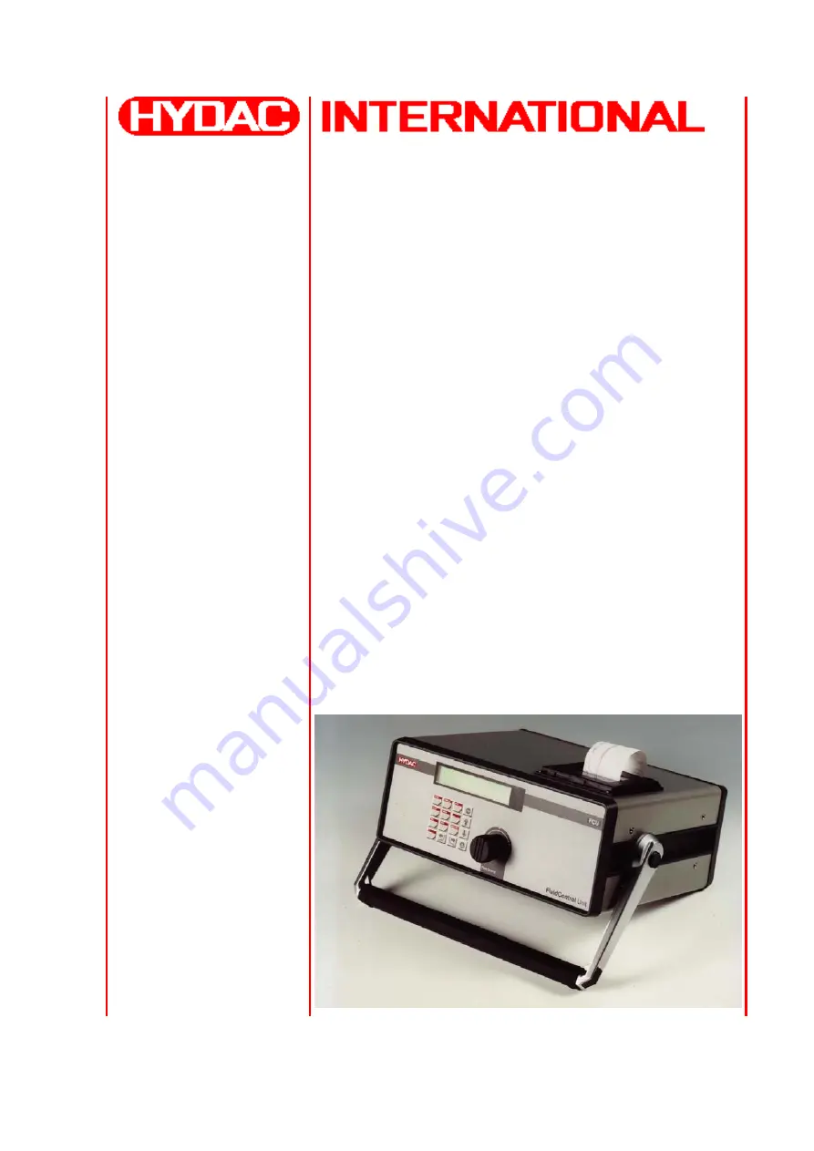
FCU 8000-1 series

FluidControl Unit

Betriebs- und Wartungsanleitung

Deutsch: Seite 1-65

FluidControl Unit

Operating and Maintenance Instruction

English: Page 66-128

FluidControl Unit

Manuel d’utilisation et d‘entretien

Francaise: Page 129-187

Doc.: 3109776  Ed.: 01/13.02.2002

Summary of Contents for FluidControl Unit FCU 8000-1 Series

Page 1: ...it Betriebs und Wartungsanleitung Deutsch Seite 1 65 FluidControl Unit Operating and Maintenance Instruction English Page 66 128 FluidControl Unit Manuel d utilisation et d entretien Francaise Page 129 187 Doc 3109776 Ed 01 13 02 2002 ...

Page 2: ...ion Exclusion of liability We made ervery endeavour to ensure the accuracy of the contents of this document However errors cannot be ruled out Consequently we accept no liability for such errors as may exist nor for any damage or loss whatsoever which may arise as a result of such errors The content of the manual is checked regularly Any corrections required will be incorporated in subsequent edit...

Page 3: ... Anschließen Einschalten und Bedienen der FCU 25 6 1 Elektrischer Anschluß 25 6 2 Hydraulischer Anschluß und Inbetriebnahme 26 6 3 Das Display der FCU 27 7 Arbeiten mit der FCU 29 7 1 Online Messbetrieb 29 7 1 1 Mode Messen 29 7 1 2 Mode Messen und Schalten 30 7 1 3 Mode Filtern bis automatisches Abreinigen durchführen 32 7 1 4 Funktion Filtern von bis automatisches Abreinigen durchführen 33 7 2 B...

Page 4: ...eldungen und Störungsbeseitigung 51 9 Wartung und Pflege 54 9 1 Filterelement 54 9 2 Rückspülen der FCU bei verstopftem Sensor 55 9 3 Neues Farbband in Drucker einsetzen 55 9 4 Neue Papierrolle in Drucker einsetzen 56 10 Ersatzteile 57 11 Zubehör 58 12 Außerbetriebnahme und Entsorgung 58 13 Lagerung 58 14 Erklärung der benutzten Begriffe der Messtechnik 59 15 Zusammenstellung der Menüs 61 16 Techn...

Page 5: ...ngen für Personen hervorrufen können Dieses Symbol kennzeichnet Sicherheitshinweise die bei Nichtbeachtung zu Gefährdungen von Personen durch elektrische Spannungen führen können Dieses Symbol gibt wichtige Hinweise für den sachgerechten Umgang mit der FCU Das Nichtbeachten dieser Hinweise kann zu Sachschäden an der FCU oder zu Umweltschäden in deren Umgebung führen Unter diesem Symbol erhalten Si...

Page 6: ...ße sind lebensgefährlich Vor dem Öffnen von Teilen der FCU muß der Netzstecker gezogen werden Tests bei geöffnetem Gehäuse dürfen nur von ausgebildeten Elektrofachkräften durchgeführt werden Dies gilt auch für Reparaturen bzw für von uns genehmigten Modifikationen an elektrischen Anlagenteilen Die Dichtheit der Schläuche und Anschlußstücke muß täglich überprüft werden Sichtkontrolle Die elektrisch...

Page 7: ...edürfen einer schriftlichen Bestätigung der Firma HYDAC Filtertechnik GmbH Alle Geräteteile in nicht einwandfreiem Zustand müssen sofort ausgetauscht werden Es dürfen nur Originalersatzteile verwendet werden Bei fremdbezogenen Teilen ist nicht gewährleistet daß sie beanspruchungs und sicherheitsgerecht konstruiert und gefertigt sind Reinigen der FCU und Entsorgung verwendeter Mittel Zum Reinigen d...

Page 8: ...setz der Länder LWG bzw sonstiger Ländervorschriften müssen beachte werden Gesetzliche Unfallverhütungsvorschriften Sicherheitsbestimmungen und Sicherheits datenblätter für Flüssigkeiten müssen in jedem Fall beachtet werden Bei Arbeiten an und in der Nähe von Hydraulikanlagen sind der Umgang mit offenem Feuer das Erzeugen von Funken und das Rauchen verboten Auffangwannen Aufsauggeräte und Bindemit...

Page 9: ... Zum Lieferumfang gehören 1 Stück FluidControl Unit FCU 8110 bzw FCU 8210 1 Stück Netz Ladegerät 1 Stück Hochdruckschlauch mit Minimessanschlüssen 1620 2000 mm lang 1 Stück Rücklaufschlauch DN7 2000 mm lang 1 Stück Kalibrierzertifikat 1 Stück Diese Bedienungsanleitung 4 Einsatzbeschränkungen Es wird empfohlen die FCU 8110 FCU 8210 nur in Verbindung mit Mineralölen oder Raffinaten deren Basis Miner...

Page 10: ... Hydraulikfilter gegen Verschmutzung geschützt ist 5 2 Leistungsbeschreibung Die FluidControl Unit FCU kann kontinuierlich die Feststoffverschmutzung von Mineralölen ermitteln Mit der FCU ist es möglich im Dauerbetrieb vollautomatisch die Reinheitsklasse nach NAS 1638 oder ISO 4406 1987 FCU 8110 bzw ISO 4406 1999 FCU 8210 oder tatsächliche Partikelzahlen zu erfassen abzuspeichern und anzuzeigen Di...

Page 11: ... FluidControl Unit Reservoir oder Rücklaufleitung des Systems Partikelsensor Druckleitung 1 350 bar Pulsationsdämpfer fest Volumenstromzähler Volumenstromregler Schutzfilter Hochdruckschlauch Druckbegrenzungsventil FCU 8110 FCU 8210 30 bar 5 µm Rücklaufschlauch eingestellter Stromregler 800 ml min Abbildung 1 Hydraulikplan der FCU ...

Page 12: ...hles die als Meßsignale von einer Auswerteelektronik 4 nach Partikelgrößen klassifiziert und gezählt werden Die zur Angabe der Verschmutzungsklasse notwendige Messung des Volumenstromes erfolgt mit einem eingebauten Volumenstromzähler 5 dessen Signale ebenfalls zu der elektronischen Auswertung 4 geführt werden Die Auswerteelektronik 4 berechnet schließlich kontinuierlich aus den Meßsignalen des op...

Page 13: ...enzanzeige steigend oder fallend Momentanwert Durchfluß nur im Störungsfall Fehlermeldungen Die FCU besitzt darüber hinaus 3 eingebaute Relais mit folgenden Funktionen Relais 1 und 2 Grenzwertschalter Wechsler Mit Relais 1 kann auch z B ein Filteraggregat angesteuert werden Relais 3 Betriebsbereitschaftssignal Schließer geschlossen wenn FCU betriebsbereit Relais 3 dient als Betriebsbereitschaftsko...

Page 14: ... Betrieb bei Störungen wie Spannungsausfall Durchflußfehler bedingt durch Druckabfall etc der Meßbetrieb nach Behebung der Störung ohne Bedienpersonal wieder starten kann Über die serielle Schnittstelle 11 können alle gemessenen und gespeicherten Meßwerte z B mittels PC ausgelesen werden Der eingebaute Drucker 14 dokumentiert die Messungen tabellarisch oder grafisch ...

Page 15: ...76 Ed 01 13 02 2002 HYDAC Filtertechnik GmbH D Seite 15 5 5 Anzeigeelemente Anschlüsse und Bedienelemente 5 5 1 Frontansicht mode memory limits ISO NAS setup print LC Display Bedienungstastatur Volumenstromregler Flow Control Partikel Abbildung 3 Frontansicht ...

Page 16: ...ement 0060 D 005 BN HC O I POWER INPUT 24 V 1 A PC CONTROL Caution Do not lock OUTLET Max 3bar 43 PSI Max 350bar INLET 5000 PSI Outlet Rücklauf zum Tank Inlet Eingang für Hydraulikmedium Verschlußdeckel Filter Ein Aus Schalter 24 V DC Anschluß für Netzadapter Serielle Schnittstelle Steueranschluß Gehäuse Erdungsklemme Abbildung 4 Rückansicht ...

Page 17: ...Relais Ansteuerung Meßwertspeicher bearbeiten Name der Meßstelle Ausdrucken Grenzwerte zur Ansteuerung Relais 1 und 2 einstellen Meßintervalle Löschen etc Online Meßwertspeicher etc von Filteraggregaten über 0 1 2 3 4 5 6 7 8 9 direkte Eingabe von nur im Eingabemodus mehrstelligen Zahlen setup Grundeinstellungen Autostart Datum Uhrzeit etc ISO ISO Code anzeigen Diese Taste reagiert nur bei laufend...

Page 18: ...hnung einfügen ok start Tasten ok start und vorwärts Blättern gleichzeitig drücken Zeichen in Messstellenbezeichnung löschen ok start Tasten ok start und rückwärts Blättern gleichzeitig drücken Powerup Menu aufrufen Tasten rückwärts und vorwärts Blättern gleichzeitig drücken Tastatursperre aktivieren deaktivieren ok start Tasten Beleuchtung und ok start gleichzeitig drücken ...

Page 19: ...als 1 Schirm 2 TXD Sendeleitung 4 RXD Empfangsleitung 8 GND Betriebserde Ein entsprechendes Kabel zum Anschluß der FCU an einen PC liegt den FCU Softwarepaketen bei Geräte mit Typenbezeichnung BUS serielle RS 485 Schnittstelle Pin Funktion des Signals 1 Schirm 2 T A Sendedaten 4 R A Empfangsdaten 8 GND Betriebserde 9 T B Sendedaten 11 R B Empfangsdaten 15 Versorgung Busabschluß 5V Die Pinbelegung ...

Page 20: ...ng wenn FCU betriebsbereit Relais 1 6 7 8 Fußkontakt Schließer 11 12 13 14 15 Benutzer programmierbar Relais 2 Benutzer programmierbar Gerät bereit Relais 3 Öffner Öffner Fußkontakt Fußkontakt Schließer Öffner Die Relaiskontakte sind mit 2A belastbar Pin 1 24 V Betriebsspannung im Akkubetrieb 12 V max 200 mA belastbar Pin 4 Betriebserde GND Pins 2 3 5 9 10 belegt für Betrieb der BottleSampling Uni...

Page 21: ...nutzer programmierte Schaltfunktion nicht erfüllt ist Kontakte 14 und 15 sind geschlossen wenn Bedingung für vom Benutzer programmierte Schaltfunktion erfüllt ist Kontakte 13 und 15 sind geschlossen wenn Bedingung für vom Benutzer programmierte Schaltfunktion nicht erfüllt ist Kontakte 11 und 12 geschlossen wenn FCU 1 betriebsbereit ist und 2 keine Störung vorhanden ist M3 Filtern bis Kontakte 7 u...

Page 22: ...folgenden Messungen mit den vom Benutzer programmierten oberen unteren Grenzen identisch sind oder diese über unterschreiten Nach Ablauf der Prüfzykluszeit werden die Kontakte 7 und 8 wieder geschlossen und die Messung erneut gestartet Kontakte 14 und 15 sind geschlossen wenn der Durchfluß außerhalb des zulässigen Bereiches liegt Erst nach Vollendung der ersten Messung Kontakte 11 und 12 geschloss...

Page 23: ... µm Kanal NAS 1 15 100 µm Kanal NAS 1 15 2 µm Kanal ISO 10 25 5 µm Kanal ISO 7 23 15 µm Kanal ISO 5 21 Durchfluß 0 150 M3 Filtriergrenze ISO 10 7 5 25 23 21 NAS 1 1 1 15 15 15 M4 Filtriergrenzen ISO 10 7 5 25 23 21 NAS 1 1 1 15 15 15 Prüfzykluszeit 0 1440 FCU 8210 min max M2 Schaltgrenzen 4 µm c Kanal ISO 10 25 6 µm c Kanal ISO 7 23 14 µm c Kanal ISO 5 21 Durchfluß 0 150 M3 Filtriergrenze ISO 10 7...

Page 24: ...d Wartungsanleitung FCU 8000 1 series Doc 3109776 Ed 01 13 02 2002 HYDAC Filtertechnik GmbH D Seite 24 5 5 6 Versorgungsspannungs Stecker Hohlstecker Ø 5 5 mm DIN 45 323 Innerer Kontakt 24V DC Äußerer Kontakt GND ...

Page 25: ...ufladbaren Akkus ausgerüstet die ein netzunabhängiges Messen Online Ausdruck und Displaybeleuchtung ausgeschaltet von bis zu 3 Stunden ermöglichen Die Akkus werden bei eingestecktem Netzteil geladen unabhängig davon ob die FCU ein oder ausgeschaltet ist Die in der FCU eingesetzten Nickel Cadmium Ni Cd Akkus sollten wegen des Memory Effekts nicht vorsorglich nachgeladen werden Der Memory Effekt wir...

Page 26: ...n Bereich für den Druckanschluß Inlet 1 350 bar liegt Der bei einer gegebenen Viskosität erforderliche Mindesteingangsdruck um einen Durchfluß von 50 ml min zu erreichen ist den Grafiken in Kapitel 16 Technische Daten zu entnehmen Mit steigender Verschmutzung des Filterelements erhöht sich der erforderliche Eingangsdruck Hochdruckschlauch zuerst an der FCU anschließen Nun das andere Ende des Hochd...

Page 27: ...mm 25 25 bis 50 mm 50 50 bis 100 mm 100 100 mm Mit den Tasten und können die angezeigten Partikelgrößen ausgewählt werden Um bereits sehr kleine Veränderungen anzuzeigen dient der Tendenzpfeil steigende Verschmutzung fallende Verschmutzung Er zeigt bereits Veränderungen an die allein durch die Klassenangabe sonst nicht bemerkt würden Mit den Tasten ISO NAS Partikel kann zwischen der Darstellung in...

Page 28: ...ne Veränderungen anzuzeigen dient der Tendenzpfeil steigende Verschmutzung fallende Verschmutzung Er zeigt bereits Veränderungen an die allein durch die Klassenangabe sonst nicht bemerkt würden Mit den Tasten ISO NAS Partikel kann zwischen der ISO Darstellung und der Anzeige von Partikelzahlen umgeschaltet werden 5 Mit den Tasten kann bei der Anzeige von Partikelzahlen zwischen differentieller Par...

Page 29: ...1 1 Mode Messen MODE Taste M1 Messen M2 Messen Schalten M3 Filtern bis M4 Filtern von bis start ok M5 BS spülen M6 Bottle Sampler Beschreibung Mit dem Mode M1 kann die Ölreinheit ohne Verwendung von Steuerfunktionen gemessen werden Typische Anwendung Kurzzeitmessung der Systemreinheit nach ISO oder NAS Norm Bedienung Messung starten Messung beenden ok start stop ...

Page 30: ...zuführen Dies könnte beispielsweise eine Alarmlampe auf einer Warte sein Kenngrößen für die Auslösung dieser Schaltvorgänge kann sein Der Durchfluß Volumenstrom Die Reinheit der Hydraulikflüssigkeit angegeben nach NAS oder ISO Norm Typische Anwendung Signalschaltung zu einer Schalttafel Warte an vollautomatischen Prüfständen Bedienung Die Auswahl der Funktion Messen Schalten erfolgt im Menü Mode M...

Page 31: ...ng Durchfluß ISO Kanal 4µm c ISO Kanal 6µm c und ISO Kanal 14µm c Beispiel 1 Schalten eines externen Aggregats außerhalb eines bestimmten Durchflußbereiches oberer und unterer Grenzwert limits Relais1 ok start ok start 2 5 15 25 50 100µ Kanal NAS Durchfluß Schaltfunktion innerhalb Band außerhalb Band überschreiten keine Funktion ok start M2 R1 Grenzwerte 40 70 ml unterschreiten LIMITS M2 R1 Meßkan...

Page 32: ...ne Grenze erreicht oder unterschritten hat von der FCU abgeschaltet wird Das unten angeführte Beispiel verdeutlicht dabei die Vorgehensweise Typische Anwendung Spülen von Hydrauliksystemen und dokumentieren der erreichten Ölreinheit durch On Line Ausdruck Bedienung MODE Taste M1 Messen M2 Messen Schalten M3 Filtern bis M4 Filtern von bis start ok M5 BS Spülen M6 Bottle Sampler Beispiel 1 OF 5C Bet...

Page 33: ...enzen befindet Das unten angeführte Beispiel verdeutlicht dabei die Vorgehensweise Typische Anwendung Langzeitüberwachung der Ölreinheit in Hydrauliksystemen und Dokumentation durch Online Ausdruck Bedienung MODE Taste M1 Messen M2 Messen Schalten M3 Filtern bis M4 Filtern von bis start ok M5 BS spülen M6 Bottle Sampler Beispiel 1 OF 5C Betrieb programmieren Abreinigen zwischen einem oberen und un...

Page 34: ...Anschluß der FCU mit dem Schnellverschlußstopfen Stecken Sie den Control Stecker der BSU in die passende Buchse der FCU ein Stecken Sie den Hohlstecker in die Spannungsversorgungsbuchse der FCU ein Eine ausführlichere Beschreibung finden Sie in der Bedienungsanleitung der BSU 8110 7 2 1 Schema der BottleSampling Unit BSU 8110 V1 FCU 8110 Druckdom Steigrohr Messbehälter M V3 S V2 R Probenglas Auffa...

Page 35: ...alten der Druckluftversorgung durch einen Kompressor vergeht bis im Druckdom ein konstanter Druck vorliegt z B 30 sec mit CompressedAir Unit CAU 8110 Druckluft Hier ist die Zeit einzustellen die nach Einschalten der Druckluftversorgung aus einem Leitungsnetz vergeht bis im Druckdom ein konstanter Druck vorliegt z B 10 sec 7 2 2 2 Setup Menü Im Setup Menü sind folgende Einstellungen vorzunehmen BS ...

Page 36: ...im Bottle Sampling Betrieb außer Funktion Hinweise im Display der FCU beziehen sich auf den Drehknopf auf der BSU Front Nach Ablauf der BS Füllzeit wird das eingestellte Spülvolumen gefördert Danach wird der Druckdom entlastet und der Meßbehälter entleert Typische Anwendung Spülen der BSU mit einer Spülflüssigkeit nach der Messung einer Ölprobe um bei der nächsten Probe eine Beeinflussung der Mess...

Page 37: ... 4 Messungen von jeweils 25 ml durchgeführt Die bei den Einzelmessungen ausgegebene Partikelzahl wird jeweils auf 100 ml hochgerechnet Verdünnung Wenn die Probe wegen zu hoher Verschmutzung oder zu hoher Viskosität verdünnt werden muß kann hier das Mischungsverhältnis eingegeben werden Die Meßergebnisse werden automatisch auf eine unverdünnte Probe hochgerechnet Der erste Wert gibt das Probevolume...

Page 38: ...ausgewählt wurde wird nach Abschluß der letzten Einzelmessung abgefragt ob eine weitere Einzelmessung Meßvolumen wie bei abgeschlossenen Einzelmessungen durchgeführt werden soll Anzeige M6 1 Messung OK beenden STOP Nach dem Abschluß der letzten Messung oder nach Betätigung der Taste STOP wird der Druckdom entlastet und der Meßbehälter entleert Die Einzelmessungen die zur Ausgabe eines gemittelten ...

Page 39: ... mit der OK START Taste abgeschlossen Bis die eingestellte Entleerungszeit abgelaufen ist erscheint im LC Display folgende Meldung Anzeige M6 fertig Entleerung Läuft bitte warten Nach Ablauf der Entleerungszeit kann gewählt werden ob das System komplett entleert werden soll Taste OK START betätigen das Absperrventil wird dann geöffnet oder ob das Öl in der Leitung bis zum Absperrventil gehalten we...

Page 40: ...den Messung kein freier Speicher mehr zur Verfügung steht wird das älteste Protokoll gelöscht Wenn nur ein Protokoll im Speicher abgelegt ist die laufende Messung werden die ältesten Messwerte überschrieben Durch die Meßstellenbezeichnung die im Protokollkopf abgespeichert wird sind Protokolle einfach zu identifizieren 7 3 1 Meßstellenbezeichnung eingeben Beschreibung In diesem Untermenüpunkt kann...

Page 41: ... a b c d e f g h i J k l m n o p q r s T u v w x y z ä é è ê ö ü ß A B C D E F G H I J K L M N O P Q R S T U V W X Y Z ok start Durch gleichzeitiges Drücken der Tasten ok start und vorwärts Blättern wird vor das gerade markierte Zeichen ein Leerzeichen in die Messstellenbezeichnung eingefügt ok start Durch gleichzeitiges Drücken der Tasten ok start und rückwärts Blättern wird das gerade markierte ...

Page 42: ...m Drucker ausgegeben Die Zeitspanne zwischen den einzelnen Meßpunkten ergibt sich aus dem eingestellten Durchfluß Bedienung MEMORY Taste Meßstelle Mittelungsintervall Selektiv löschen Alles löschen ok start Meßstelle ändern Typische Anwendung Überwachung der Ölreinheit an Hydraulikaggregaten mit der Möglichkeit an der gleichen Meßstelle über einen längeren Zeitraum Vergleichsmessungen durchzuführe...

Page 43: ... Die Anzeige des jeweils aktuellen einzelnen Meßwertes erfolgt immer noch zur Information im Display der FCU gespeichert und ausgedruckt werden jedoch nur die Mittelwerte der innerhalb des eingestellten Intervalls abgeschlossenen Messungen Bedienung MEMORY Taste Meßstelle Mittelungsintervall Selektiv löschen Alles löschen ok start Meßstelle ändern Typische Anwendungen Kontinuierliche Langzeitüberw...

Page 44: ... vom Anwender Probemessungen durchgeführt deren Archivierung für spätere Dokumentationen oder Vergleichsmessungen nicht erforderlich ist Bedienung MEMORY Taste Meßstelle Mittelungsintervall Selektiv löschen Alles löschen ok start Meßstelle ändern Beispiel 1 Löschen gespeicherter Protokolle memory MEMORY Meßstelle memory selektiv löschen ok start 0 1 2 3 4 5 6 7 8 9 oder ok start memory alles lösch...

Page 45: ...ung eingeben 7 4 Drucken Beschreibung Mit dieser Anwendung ist es dem Benutzer möglich Meßergebnisse z B unmittelbar nach der Messung auszudrucken oder aber bereits vorhandene Meßwerte Protokolle auszuwählen und auszudrucken Darüber hinaus können alle Parameter der FCU sowie eine Inhaltsangabe der gespeicherten Protokolle ausgedruckt werden PRINT Taste Protokolle Inhaltsangabe Alle Parameter Papie...

Page 46: ...iste Grafik ok start Ausdruck von Partikel NAS ISO ok start PRINT Online Ausdruck Online Ausdruck aus ein ok start 7 4 2 Drucken gespeicherter Protokolle Beschreibung Mit dieser Betriebsart ist es dem Anwender möglich in der Vergangenheit durchgeführte Messungen aufzurufen und auszudrucken Das Untermenü erlaubt dabei die Auswahl nach verschiedenen Suchfunktionen Die Protokollnummer wird als fortla...

Page 47: ...mer vorgegeben Diese Werte können mit den Zifferntasten und den Tasten und geändert werden Bei Protokollauswahl nach Datum Meßstelle oder Datum Meßstelle können mit den Tasten und die vorhandenen Werte durchgeblättert werden Bei Bottle Sampling Messung wird zusätzlich zu den Ergebnissen der Einzelmessungen ein gemitteltes Gesamtergebnis ausgegeben Beispiel 2 Ausdruck einer Bottle Sampling Messung ...

Page 48: ...orlaufzeit SETUP Taste Akkuspannung Zusatzmessung ja Die FCU starten nach dem Einschalten automatisch mit der Messung im eingestellten Meßmodus Autostartfunktion Autostart nein Der Start einer Messung muß manuell ausgelöst werden ja Fällt der Volumenstrom durch den Sensor auf den Wert 0 ab so wird die Messung abgebrochen und die FCU abgeschaltet Abbruch bei Q 0 nein Fällt der Volumenstrom durch de...

Page 49: ... Datum und Uhrzeit werden angezeigt und können verändert werden Busadresse Standardeinstellung ist 1 diese Einstellung sollte nicht verändert werden Sind mehrere Geräte mit DIN Meßbus Schnittstelle Typenschlüssel BUS an einem Bus angeschlossen muß jedem Gerät eine Busadresse zwischen 1 und 31 zugewiesen werden Eine Adresse darf nicht zweimal vergeben werden Betriebsstunden Die Betriebsstunden des ...

Page 50: ...ht geändert werden müssen Sprache für die Anzeigetexte und die Ausdrucke wählen Zur Auswahl stehen Deutsch Englisch Französisch und eine frei programmierbare Sprache in Verbindung mit Software FCUDESK Parameter für den Betrieb mit der BSU 8110 siehe Kapitel 7 2 Bottle Sampling Betrieb Das Menü wird angewählt durch das gleichzeitige Drücken der beiden Blättern Tasten M6 Bottle Sampler nach Einschal...

Page 51: ...e Selbstüberwachungsfunktion der FCU hat einen Prüfsummenfehler bei einem oder mehreren abgespeicherten Protokollen festgestellt Ursachen Eine starke elektromagnetische Störung hat den Meßwertspeicher verändert die interne Speicherbatterie ist verbraucht Die defekten Protokolle werden automatisch gelöscht d h nach dem nächsten Einschalten erscheint diese Meldung nicht mehr wenn es sich um eine kur...

Page 52: ...Gerät ggf zur Reparatur einschicken Durchflußfehler Korrigieren 15 ml Der Partikelsensor Durchfluß ist kleiner als der für eine Messung notwendige Minimalwert von 20 ml min Volumenstromregler nach rechts drehen in Richtung bis Meßbetrieb startet Durchflußfehler Korrigieren 250 ml Der Partikelsensor Durchfluß ist größer als der für eine Messung notwendige Maximalwert von 80 ml min Volumenstromregle...

Page 53: ...hen neu laden der interne Speicher für die Sprachen ist durch eine Störung teilweise verändert worden Die interne Speicherbatterie ist verbraucht mit der PC Software FCUDESK die FCU Sprachen neu in die FCU übertragen falls sich der Fehler wiederholt Gerät zu Reparatur einschicken Gerätekennung defekt Die internen Gerätekennungen im EEPROM sind durch eine Störung verändert worden nicht unbedingt no...

Page 54: ...enzdruck von 2bar kann nicht erreicht werden so erfolgt keine Anzeige auf dem Display In diesem Fall erfolgt lediglich die Meldung Durchflußfehler Filterelement wechseln Geeigneten Behälter zum Auffangen des Restöls bereit stellen Vor dem Wechsel des Elements ist die FCU von der Anlage zu trennen Vorsicht Minimeßleitung zuerst von der Anlage trennen Filtertopfverschlußschraube an der Rückseite des...

Page 55: ...en und ganz nach hinten klappen b An der rechten Seite des Farbbandes auf Push drücken bis sich das Farbband löst c Altes Farbband entnehmen d Neues Farbband mit der Beschriftung Push nach rechts in die Hand nehmen und über das Papier fädeln Das Papier muß sich zwischen Plastikgehäuse und Farbband befinden e Das Farbband mit der linken Seite Farbbandantrieb zuerst einsetzen dann auf die rechte Sei...

Page 56: ... daß sie sich von der linken Seite gesehen gegen den Uhrzeigersinn abwickelt das Papier muß auf der Hinterseite abgewickelt werden können e Papieranfang unter die 1 Metallplatte in der sich die Transportrolle befindet schieben bis Papieranfang zwischen Transportrolle und 2 Metallplatte eingeklemmt ist f Grünen Knopf drücken und halten dabei die FCU einschalten und warten bis das Druckerpapier ca 3...

Page 57: ...eckel 349 204 Verbindungskabel FCU PC 349 155 Papierrollensatz Drucker 5 St Rollendurchmesser 50 mm Rollenbreite 58 mm 349 156 Farbband Drucker Typ Epson ERC 09 P 6003 720 Hochdruck Meßschlauch DN 2 5000 mm lang 682 859 Hochdruck Meßschlauch DN 2 2000 mm lang 349 151 Rücklaufschlauch DN 7 2000 mm lang 125 1558 Rücklaufschlauch DN 7 5000 mm lang 349 152 Netz Ladegerät 230 V Europa Stecker 349 208 N...

Page 58: ...eservoirExtraction Unit REU 1410 302 8133 ReservoirExtraction Unit REU 1430 12 Außerbetriebnahme und Entsorgung Bei der Außerbetriebnahme und oder Entsorgung der FCU müssen alle Lokalen Richtlinien und Auflagen bezüglich Arbeitssicherheit und des Schutzes der Umwelt berücksichtigt werden Insbesondere gilt dies für das im Gerät befindliche Öl ölverschmierte und elektronische Bauteile 13 Lagerung Vo...

Page 59: ...eichert werden Im Display werden die aktuellen Meßwerte angezeigt Beispiel 10 Minuten aber auch z B 24 Std 1440 Minuten möglich Meßwertspeicher Memory Eine einmal gestartete Messung läuft kontinuierlich ab d h es fallen ständig neue Werte an die nacheinander als Protokollzeilen im Meßwertspeicher abgelegt werden Ist der Speicher voll werden die ältesten Meßwerte mit den neuesten überschrieben roll...

Page 60: ...cherprotokoll 6 HYDAC FCU 8110 vom 20 10 1999 8 32 bis 20 10 1999 10 42 Mittelungsintervall 10 min Anzahl der Protokollzeilen 13 Dauer der Meßreihe 2 10 Protokollzeile Eine Protokollzeile besteht aus dem Zeitpunkt und den Ergebnissen 4 Partikelkanäle und Durchfluß einer Messung Die FCU kann bis zu 3000 Protokollzeilen speichern ...

Page 61: ...ervall Selektiv löschen Alles löschen Meßstelle ändern PRINT Taste Protokolle Inhaltsangabe Alle Parameter Papiervorschub Intern Extern Online Ausdruck Ausdruck abbrechen BS Protokolle LIMITS Taste M2 Relais 1 M2 Relais 2 M3 Filtern bis M4 Filtern von bis M5 Spülvolumen M6 Probenvolumen BS Druckversorgung Autostart Abbruch bei Q 0 Datum Uhrzeit Busadresse Betriebsstunden Pumpenvorlaufzeit SETUP Ta...

Page 62: ...eriegepufferter Datenspeicher Kann bis zu 3000 Meßwerte aufnehmen Eingangs Betriebsdruck Druckanschluß Inlet 1 350 bar Rücklauf Outlet max 3 bar Gegendruck Anschlüsse Rückseite Inlet Minimeßkupplung System 1620 Outlet DN 7 Stecknippel Rücklauf Outlet Volumenstrom ca 800 ml min bei 350 bar Meßvolumenstrom 20 80 ml min Zulässiger Viskositätsbereich 5 800 mm2 s Medientemperaturbereich 0 70 Celsius Sp...

Page 63: ...ungsanleitung FCU 8000 1 series Doc 3109776 Ed 01 13 02 2002 HYDAC Filtertechnik GmbH D Seite 63 Lagertemperaturbereich 40 70 Celsius rel Feuchte max 90 nicht kondensierend Schutzklasse 1 Schutzart IP40 Gewicht ca 14 kg ...

Page 64: ...ng FCU 8000 1 series Doc 3109776 Ed 01 13 02 2002 HYDAC Filtertechnik GmbH D Seite 64 17 Adressen 17 1 Versandadresse für Nachkalibrierungen und Reparaturen HYDAC Servicetechnik Abt Kundendienst Hauptstraße 27 D 66128 Saarbrücken ...

Page 65: ...Betriebs und Wartungsanleitung FCU 8000 1 series Doc 3109776 Ed 01 13 02 2002 HYDAC Filtertechnik GmbH D Seite 65 18 CE Zertifikat ...

Page 66: ...necting switching on and operating the FCU 88 6 1 Electrical connection 88 6 2 Hydraulic connection and commissioning 89 6 3 The FCU display 90 7 Working with the FCU 92 7 1 Online measurement 92 7 1 1 Measurement mode 92 7 1 2 Measuring and switching mode 93 7 1 3 Mode Filter to carry out automatic filtration 95 7 1 4 Function Filter from to carry out automatic filtration 96 7 2 Bottle sampling o...

Page 67: ...troubleshooting 114 9 Maintenance and service 117 9 1 Filter element 117 9 2 Back flushing the FCU when the sensor is blocked 118 9 3 To insert new ribbon cartridge in the FCU printer 118 9 4 To insert new paper roll in the printer 119 10 Spare parts 120 11 Accessories 121 12 Decommissioning and disposal 121 13 Storage 121 14 Glossary of terms used in measurement technology 122 15 Overview of the ...

Page 68: ...f not observed can endanger personal safety This symbol indicates safety recommendations which if not observed can endanger personal safety through electric shock This symbol gives important information on the correct usage of the FCU Failure to observe these recommendations can lead to damage to the FCU or environmental damage to the surrounding area Where you see this sign you will find user tip...

Page 69: ...ion The mains supply unit of the FCU operates with voltages up to 250 Volt AC 50 60Hz Such voltages are highly dangerous Before opening sections of the FCU the mains plug must be disconnected Tests must not be carried out when the housing is open except by a qualified electrician The same applies to repairs or modifications carried out with our approval on electrical system parts The leak tightnes...

Page 70: ...tional and conversion work must have written confirmation from HYDAC Filtertechnik GmbH All components which are not in perfect condition must be replaced immediately Original spare parts only must be used For parts obtained elsewhere we cannot guarantee that they are designed and manufactured to a specification appropriate for the load and for safety considerations Cleaning the FCU and disposal o...

Page 71: ...perator to comply with the water regulations of the country concerned Statutory accident prevention regulations safety regulations and safety data sheets for fluids must be observed When working on or in the vicinity of hydraulic systems naked flames spark generation and smoking are forbidden Drip trays suction equipment and absorbent material should be to hand Hydraulic oils and water polluting f...

Page 72: ...ed The following items are supplied 1 off FluidControl Unit FCU 8110 FCU 8210 1 off mains charging unit 1 off high pressure hose with Minimess connections 1620 2000 mm in length 1 off return line hose DN7 2000 mm in length 1 off calibration certificate 1 off this operating manual 4 Application restrictions We recommend that the FCU 8110 FCU 8210 is used only with mineral oils or raffinates based o...

Page 73: ...rement flow rate which is protected from contamination by a hydraulic filter 5 2 Performance description The FluidControl Unit FCU can monitor solid particle contamination in mineral oils on a continuous basis Using the FCU it is possible to record store and display the cleanliness class to NAS 1638 or ISO 4406 1987 FCU 8110 ISO 4406 1999 FCU 8210 or actual particle quantities fully automatically ...

Page 74: ...draulic circuit FluidControl Unit reservoir or return line of the system particle sensor pressure line 1 350 bar pulsation damper fixed flow rate meter flow control valve filter high pressure hose pressure relief valve FCU 8110 FCU 8210 30 bar 5 µm return line hose current regulator 800 ml min Figure 1 Hydraulic circuit of FCU ...

Page 75: ...n classified and counted according to particle size as measurement signals by the evaluation electronics 4 The measurement of the flow rate which is required for calculating the contamination class is achieved with a built in flow meter 5 whose signals are also fed to the evaluation electronics 4 Finally the evaluation electronics 4 calculate the number of particles and NAS or ISO contamination cl...

Page 76: ...cle size channels trend display rising or falling instantaneous flow rate value only in the event of breakdown error messages The FCU also has 3 built in relays with the following functions Relays 1 and 2 limit switches change over contacts With relay 1 a filtration unit for example can also be controlled Relay 3 device ready signal normally open contact closed when FCU is ready for operation Rela...

Page 77: ...akdowns such as power failure flow errors due to pressure drop etc during permanent online operation measurement can resume once the fault has been eliminated without operator intervention All measured and stored values can be viewed via the serial interface 11 e g using a PC The built in printer 14 logs the measurements in table or graph format ...

Page 78: ...oc 3109776 Ed 01 13 02 2002 HYDAC Filtertechnik GmbH E Page 78 5 5 Display elements connections and operating elements 5 5 1 Front view mode memory limits ISO NAS setup print LC Display keypad flow control valve Fl o w C on t rol Partikel Figure 3 Front view ...

Page 79: ... Filter Element 0060 D 005 BN HC O I POWER INPUT 24 V 1 A PC CONTROL Caution Do not lock OUTLET Max 3bar 43 PSI Max 350bar INLET 5000 PSI outlet return line to tank inlet inlet for hydraulic fluid filter cover on off switch 24 V DC connection for mains charging unit serial interface control port case earth connector Figure 4 Rear view ...

Page 80: ...ay control edit log memory name of measuring poit print adjust limit values for control via relay 1 and 2 averaging interval deletion etc online stored logs etc of filtration units 0 1 2 3 4 5 6 7 8 9 direct input of digits input mode only numbers with several setup edit setup Autostart Date timet etc ISO display results in ISO Code this key only functions during an active measurement NAS display ...

Page 81: ... point designation ok start Press ok start key and scroll forward key simultaneously Delete character in measuring point designation ok start Press ok start key and scroll back key simultaneously Call up power up menu Press scroll back and scroll forward keys simultaneously Activate deactivate keyboard lock ok start Press illumination key and ok start key simultaneously ...

Page 82: ...en 2 TXD transmitter line 4 RXD receive line 8 GND operating earth An appropriate cable for connecting the FCU to a PC is enclosed with the FCU software package Units with designation BUS serial interface RS 485 Pin Function of the signal 1 screen 2 T A transmit data 4 R A receive data 8 GND operating earth 9 T B transmit data 11 R B receive data 15 bus terminal supply 5V The pin connections corre...

Page 83: ...ignment switching position when FCU ready for operation Relay 1 6 7 8 common N O 11 12 13 14 15 programmable by user Relay 2 programmable by user device ready Relay 3 N C N C common common N O N C The relay contacts capacity is 2A Pin 1 24 V operating voltage 12 V battery operation max 200 mA load Pin 4 operating earth GND Pins 2 3 5 9 10 are in use for operating the BottleSampling Unit BSU 8110 ...

Page 84: ... are closed if condition for switching function programmed by user is not fulfilled Contacts 14 and 15 are closed if condition for switching function programmed by user is fulfilled Contacts 13 and 15 are closed if condition for switching function programmed by user is not fulfilled Contacts 11 and 12 closed if FCU is 1 ready for operation and 2 functioning correctly M3 Filter to Contacts 7 and 8 ...

Page 85: ...ed values of 5 consecutive measurements are identical to the upper lower limits programmed by the user or exceed those limits Following the test cycle time contacts 7 and 8 are closed again and measurement starts again Contacts 14 and 15 are closed if flow rate is outside of the allowed range after completion of the first measurement Contacts 11 and 12 closed if FCU is 1 ready for operation 2 func...

Page 86: ...channel NAS 1 15 100 µm channel NAS 1 15 2 µm channel ISO 10 25 5 µm channel ISO 7 23 15 µm channel ISO 5 21 Flow rate 0 150 M3 filtration limit ISO 10 7 5 25 23 21 NAS 1 1 1 15 15 15 M4 filtration limits ISO 10 7 5 25 23 21 NAS 1 1 1 15 15 15 Test cycle time 0 1440 FCU 8210 min Max M2 switching limits 4 µm c channel ISO 10 25 6 µm c channel ISO 7 23 14 µm c channel ISO 5 21 Flow rate 0 150 M3 fil...

Page 87: ... and Maintenance Instruction FCU 8000 1 series Doc 3109776 Ed 01 13 02 2002 HYDAC Filtertechnik GmbH E Page 87 5 5 6 Supply voltage plug Jack plug Ø 5 5 mm DIN 45 323 Internal contact 24V DC External contact GND ...

Page 88: ... chargeable batteries which enable measurement independent of the mains Online printing and Display illumination switched off for up to 3 hours The batteries are re charged when connected to the mains irrespective of whether the FCU is switched on or off The nickel cadmium Ni Cd batteries fitted in the FCU should not be charged before they are empty because of the memory effect The memory effect a...

Page 89: ...nection Inlet 1 350 bar The minimum inlet pressure required at a given viscosity to achieve a flow rate of 50 ml min can be obtained from the graphs under Point 16 Technical specifications As the contamination of the filter element increases so too does the required inlet pressure Connect the high pressure hose to the FCU first Then secondly connect the other end of the high pressure hose to the M...

Page 90: ...ted 2 2 to 5 mm 5 5 to 15 mm 15 15 to 25 mm 25 25 to 50 mm 50 50 to 100 mm 100 100 mm The displayed particle sizes can be selected by pressing the und keys The trend arrow indicates very small changes increasing contamination decreasing contamination It indicates changes which would not otherwise be obvious from the class indication alone Using the keys ISO NAS Partikel you can switch between disp...

Page 91: ...e 4µm c 6µm c 14µm c The trend arrow indicates very small changes increasing contamination decreasing contamination It indicates changes which would not otherwise be obvious from the class indication alone Using the keys ISO Partikel you can switch between displaying in ISO coding and the display of particle quantity 5 When displaying particle quantity by using the keys you can choose between diff...

Page 92: ... Measurement mode MODE key M1 Measure M2 Measure switch M3 Filter to M4 Filter from to start ok M5 Rinse BS M6 Bottle sampler Description Mode M1 can be used to measure the oil cleanliness without using control functions Typical application Short term measurement of the system cleanliness to ISO or NAS standards Operation Start measurement Stop measurement ok start stop ...

Page 93: ...lays This could for example be a warning light at an observation point Parameters for triggering these switching processes can be The flow rate The cleanliness of the hydraulic fluid given according to NAS or ISO standard Typical application Signal switching to a control panel observation point on fully automatic test rigs Operation The function Measure switch is selected from the Mode menu MODE k...

Page 94: ...O channel 4µm c ISO channel 6µm c and ISO channel 14µm c Example 1 Switching an external unit outside a specified flow rate range upper and lower limit limits Relay 1 ok start ok start 2 5 15 25 50 100µ channel NAS Flow rate Switching function within range outside range exceed no function ok start M2 R1 limits 40 70 ml fall below LIMITS M2 R1 Measurement channel 0 1 2 3 4 5 6 7 8 9 oder ok start 2...

Page 95: ...e measurements has reached or dropped below the given limit it is switched off by the FCU The example set out below explains the process Typical application To flush hydraulic systems and log the oil cleanliness achieved via online print out Operation MODE key M1 Measure M2 Measure switch M3 Filter to M4 Filter from to start ok M5 Rinse BS M6 Bottle sampler Example 1 Program OF 5C operation filter...

Page 96: ... within the given limits The example given below clarifies the process Typical application Long term monitoring of the oil cleanliness in hydraulic systems and logging via online print out Operation MODE key M1 Measure M2 Measure switch M3 Filter to M4 Filter from to start ok M5 Rinse BS M6 Bottle sampler Example 1 Program OF 5C operation filter between an upper and a lower limit limits ok start M...

Page 97: ...U with a bayonet quick release plug Insert the control plug of the BSU into the matching socket of the FCU Insert the jack plug in the voltage supply socket of the FCU A more detailed description can be found in the operating instructions for the BSU 8110 7 2 1 Diagram of the BottleSampling Unit BSU 8110 V1 FCU 8110 pressure chamber suction tube measurement tank M V3 S V2 R sample bottle drip tray...

Page 98: ... be achieved in the pressure chamber after switching on the compressed air supply via a compressor e g 30 sec using Compressed Air Unit CAU 8110 Compressed air At this point you must pre set the time required for a constant pressure to be achieved in the pressure chamber after switching on the compressed air supply from the ring main e g 10 sec 7 2 2 2 Setup menu The following settings must be mad...

Page 99: ...TS menu When the START key is pressed pressure in the pressure chamber builds up first Then the shut off valve is opened and the flushing fluid begins to flow The flow rate is adjusted using the control knob on the front of the BSU The flow control valve on the FCU 8110 is de activated during bottle sampling operation Messages in the FCU display relate to the control knob on the front of the BSU O...

Page 100: ...to be divided can be set to 1 10 For example for a measurement volume of 100 ml and 4 measurements per sample 4 measurements of 25 ml each will be carried out The resultant quantity of particles from each individual measurement is projected for 100 ml each Dilution ratio If the sample has to be diluted due to excessive contamination or high viscosity the mixture ratio can be input here The measure...

Page 101: ...es was selected in the Setup Menu under additional measurement you will be asked whether an additional individual measurement measurement volumes as for completed individual measurements should be carried out once the last individual measurement has ended Display M6 1 test OK finish STOP Once the last measurement has ended or when the STOP key has been pressed the pressure in the chamber is releas...

Page 102: ...s finished with the OK START key and the print out starts Until the set draining time has elapsed the following message appears in the LC Display Display M6 Done Draining Please wait Once the drainage time has elapsed you can choose whether the system should be drained completely press OK START key the shut off valve is then opened or whether the oil should be retained in the pipe as far as the sh...

Page 103: ...deleted If only one log is stored in the memory the active measurement the oldest measurements will be overwritten Logs are easy to identify by the measurement point designation stored in the log heading 7 3 1 Inputting the measurement point designation Description The alphanumeric measurement point designation can be entered in this sub menu point and stored MEMORY key Measurement point Averaging...

Page 104: ...x y z ä É è ê ö ü ß A B C D E F G H I J K L M N O P Q R S T U V W X Y Z ok start By pressing the ok start and scroll forward keys simultaneously a space is inserted in the measurement point designation in front of the symbol just highlighted ok start By pressing the ok start and scroll back keys simultaneously the symbol just highlighted is deleted from the measurement point designation ...

Page 105: ... printed out on the printer The period of time between the individual measurement points is determined by the pre set flow rate Operation MEMORY key Measurement point Averaging interval Selective deletion Delete all ok start Change meas point Typical application Monitoring the oil cleanliness on hydraulic units with the possibility of running comparative measurements at the same measurement point ...

Page 106: ...he averaging interval Each current individual measurement value is always displayed for information on the FCU display however only the average values of the measurements taken within the pre set interval are stored and printed out Operation MEMORY key Measurement point Averaging interval Selective deletion Delete all ok start Change meas point Typical applications Continuous long term monitoring ...

Page 107: ...CU Typical application Sample measurements were made which do not need to be archived for later documentation or comparative measurements Operation MEMORY key Measurement point Averaging interval Selective deletion Delete all ok start Change meas point Example 1 Deleting stored logs memory MEMORY Meas point memory selective deletion ok start 0 1 2 3 4 5 6 7 8 9 or ok start memory delete all ok sta...

Page 108: ...ure see 7 3 1 Inputting the measurement point designation 7 4 Printing Description Using this application the user can print out measurement results e g immediately after measuring or else select and print out measured values logs already available Moreover all parameters of the FCU or a directory of the stored logs can be printed out PRINT key Logs Directory All parameters Paper feed Internal ext...

Page 109: ...raph ok start Print out of Particle NAS ISO ok start PRINT Online print out Online print out off on ok start 7 4 2 Printing out stored logs Description Using this mode of operation enables the user to call up measurements carried out in the past and to print them out The sub menu enables selection according to different search functions The log number is stored continuously as a consecutive number...

Page 110: ...l value These values can be altered using the number keys and the and keys When selecting logs according to date measuring position or date measuring position the available values can be scrolled through using the and keys When measuring using the Bottle Sampling Unit in addition to the results of the individual measurements an average overall result is also produced Example 2 Printing out a Bottl...

Page 111: ...mp pre run time SETUP Taste Battery voltage Additional test yes The FCU starts automatically after switching on with measuring in the pre set measurement mode Autostart function Autostart no Start of measurement must be triggered manually yes If the flow rate through the sensor falls to the value 0 then measurement is aborted and the FCU switched off Abort at Q 0 no If the flow rate through the se...

Page 112: ...d Bus address Standard setting is 1 this setting should not be altered If several units with DIN measurement bus interfaces model code BUS are connected to one bus a bus address between 1 and 31 must be allocated to each unit The same address must not be allocated twice Operating hours The operating hours of the unit are displayed Battery voltage The actual charging condition of the batteries is d...

Page 113: ...ormally need to be altered Select language for the display texts and print outs German English French and one customer programmable language in conjunction with FCUDESK software are available Parameters for operation with the BSU 8110 see point 7 2 Bottle sampling operation The menu is called up by pressing both scroll keys simultaneously M6 Bottle Sampler after switching on press simultaneously l...

Page 114: ...s detected a check sum error for one or more stored logs Causes A strong electromagnetic interference has changed the measured value memory The internal back up battery is discharged The defective logs are automatically deleted This means that after the next power up this message is not displayed again if this was just a short term interference If this message is displayed several times the intern...

Page 115: ...e direction until measurement starts Filter contaminated The internal protection filter for the flow control valve of the FCU is clogged Replace FCU filter element External input activated this message only occurs with the OF5C filtration unit The clogging indicator fitted in the OF5C has been activated the OF5C filter is clogged Replace OF5C filter element Internal printer not ready Paper roll em...

Page 116: ...n the EEPROM have been altered due to electrical interference This is not a critical error because these codes do not affect the proper function of the FCU Ship FCU to HYDAC for repair if necessary No BS logs selected You have tried to print out a BS log but the none of the selected log s was produced using the Bottle Sampling Unit Print log s in the Print Logs menu ...

Page 117: ...ut a differential pressure of 2 bar is not reached then no message will appear in the display In this case a message indicating flow error will appear Changing the filter element Prepare suitable container to collect the residual oil Before changing the element disconnect the FCU from the system Caution First disconnect Minimess hose from the system unscrew filter bowl lock nut on the back of the ...

Page 118: ...ter a Lift printer cover at the front and fold back fully b On the right hand side of the ribbon cartridge push where marked Push until the cartridge is released c Remove old cartridge d Hold the new cartridge with the Push label on the right and feed the paper through The paper must be between ribbon and plastic cartridge e Place the cartridge left side ribbon drive in first then push where marke...

Page 119: ...lace new paper roll in the printer so that when viewed from the left hand side paper unrolls anti clockwise it must be possible to unroll the paper from the back e Feed paper edge under the first metal plate in the feed roller and push until it is gripped between the feed roller and the second metal plate f Press and hold green button while switching on the FCU and wait until approximately 3 cm of...

Page 120: ...plate 349 204 Connection cable FCU PC 349 155 Paper roll kit for printer 5 pcs Diameter of roll 50 mm Roll width 58 mm 349 156 Ribbon cartridge for printer Type Epson ERC 09 P 6003 720 High pressure measuring hose DN 2 5000 mm long 682 859 High pressure measuring hose DN 2 2000 mm long 349 151 Return line hose DN 7 2000 mm long 125 1558 Return line hose DN 7 5000 mm long 349 152 Mains Charging uni...

Page 121: ...river 349 790 Reservoir Extraction Unit REU 1410 302 8133 Reservoir Extraction Unit REU 1430 12 Decommissioning and disposal When decommissioning and or disposing of the FCU all local guidelines and conditions concerning safety at work and the protection of the environment must be taken into consideration This applies in particular to the oil contained in the unit to components coated in oil and t...

Page 122: ...he average value will be printed out and stored In the display the actual measurement values are displayed Example 10 minutes but also for example 24 hours 1440 minutes possible Memory Once started a measurement runs continuously i e new values are obtained constantly which are filed one after the other as log lines in the measurement value memory If the memory is full the oldest measurement value...

Page 123: ...ge 123 Example Stored log 6 HYDAC FCU 8110 from 20 10 1999 8 32 to 20 10 1999 10 42 Averaging interval 10 min Number of log lines 13 Duration of measurement range 2 10 Log line A log line is made up of the time and the results 4 particle channels and flow rate of a measurement The FCU can store up to 3000 log lines ...

Page 124: ...veraging interval Selective deletion Delete all Change meas point PRINT key Logs Directory All parameters Paper feed Internal external Online printing Abort printing BS logs LIMITS key M2 Relay 1 M2 Relay 2 M3 Filter to M4 Filter from to M5 Rinse BS M6 Bottle sampler BS pressure supply Autostart Abort at Q 0 Date time Bus address Operating hours Pump pre run time SETUP key Battery voltage Addition...

Page 125: ...with battery back up Can record up to 3000 measured values Input operating pressure Pressure port Inlet 1 350 bar Return line Outlet max 3 bar back pressure Ports Rear Inlet Minimess coupling system 1620 Outlet DN 7 plug Return line Outlet flow rate approx 800 ml min at 350 bar Measurement flow rate 20 80 ml min Permissible viscosity range 5 800 mm2 s Temperature range of fluid 0 70 Celsius Voltag...

Page 126: ...truction FCU 8000 1 series Doc 3109776 Ed 01 13 02 2002 HYDAC Filtertechnik GmbH E Page 126 Temperature range for storage 40 70 Celsius Relative humidity max 90 non condensing Protection class 1 Safety type IP40 Weight approx 14 kg ...

Page 127: ...struction FCU 8000 1 series Doc 3109776 Ed 01 13 02 2002 HYDAC Filtertechnik GmbH E Page 127 17 Addresses 17 1 Address for Re Calibration and Repair HYDAC Servicetechnik Abt Kundendienst Hauptstraße 27 D 66128 Saarbrücken Germany ...

Page 128: ...Operating and Maintenance Instruction FCU 8000 1 series Doc 3109776 Ed 01 13 02 2002 HYDAC Filtertechnik GmbH E Page 128 18 CE Certificate ...

Page 129: ... Tension d alimentation prise 149 6 Raccordement connexion et utilisation du FCU 150 6 1 Raccordement électrique 150 6 2 Raccordements hydrauliques et mise en service 151 6 3 L écran d affichage du FCU 152 7 Travailler avec le FCU 153 7 1 Fonctionnement de mesure en ligne 153 7 1 1 Mode Mesure 153 7 1 2 Mode Mesurer et commuter 154 7 1 3 Mode Filtrer jusqu à effectuer un rinçage automatique 156 7 ...

Page 130: ... réglages de base 173 7 6 Menu POWER UP 175 8 Messages d erreur et élimination des défauts 176 9 Maintenance et entretien 179 9 1 Elément filtrant 179 9 2 Installer un nouveau ruban encreur dans l imprimante 180 9 3 Mise en place d un nouveau rouleau de papier 180 9 4 Rinçage à contre courant du FCU en cas de capteur encrassé 180 10 Pièces de rechange 181 11 Accessoires 182 12 Mise hors service et...

Page 131: ...n danger pour les personnes Ce symbole accompagne les recommandations de sécurité dont le dont respect expose les personnes à des tensions électriques dangereuses Ce symbole signale les consignes importantes pour une utilisation appropriée du FCU Le non respect de ces consignes peut entraîner des dommages matériels au niveau du FCU ou des dommages à l environnement proche de celui ci Ce symbole in...

Page 132: ...t ordre sont dangereuses Avant d ouvrir les parties du FCU 8110 il faut retirer le cordon d alimentation Des tests avec un appareil décapoté ne peuvent être réalisés que par des électriciens qualifiés Il en est de même pour des réparations ou des modifications approuvées par nous sur les parties électriques de l installation L étanchéité des flexibles et des embouts de raccordement doivent être co...

Page 133: ...FILTERTECHNIKGmbH Tous les composants détériorés ou abîmés doivent être immédiatement remplacés On ne peut utiliser que des pièces de rechange originales Dans le cas d utilisation de pièces étrangères il n est pas garanti qu elles soient construites et achevées conformément aux exigences et normes de sécurité Nettoyage du FCU et élimination du fluide utilisé Attention certains produits de nettoyag...

Page 134: ...ccidents des dispositions et des fiches signalétiques en matière de sécurité doivent être respectées dans tous les cas Pour des travaux sur ou à proximité d une installation hydraulique il est interdit de manier un feu ouvert de produire des étincelles et de fumer Des cuves de rétention des aspirateurs industriels et des agglomérants doivent être mis à disposition Des huiles hydrauliques et des fl...

Page 135: ...mplète L emballage contient 1 FluidControl Unit FCU 8110 1 Cordon d alimentation chargeur 230 V AC 1 Flexible haute pression avec raccord Minimess 1620 longueur 2000 mm 1 Flexible retour DN7 longueur 2000 mm 1 Certificat de calibrage 1 Cette notice d entretien et d utilisation 4 Spécifications d utilisation Il est recommandé d utiliser le FCU avec des huiles minérales ou des produits raffinés à ba...

Page 136: ...llution par un filtre monté en amont de celui ci 5 2 Description des performances L unité de contrôle des fluides FCU est destinée à déterminer en continu le niveau de pollution par particules solides contenues dans les huiles minérales Il permet sans interruption du cycle de déterminer automatiquement la classe de pollution selon NAS 1638 ou ISO 4406 de les enregistrer ou de des afficher Les vale...

Page 137: ...nit Réservoir ou conduite retour de système Capteur de particules Conduite haute pression 1 350 bar Amortisseur de pulsations Régulateur Compteur volumétrique Régulateur de débit Filtre de protection Flexible haute pression Limiteur de pression FCU 8110 30 bar 5 µm Flexible retour de débit à débit préréglé 800 ml min Figure 1 Schéma hydraulique du FCU 8110 ...

Page 138: ... polluantes contenues dans le flux de fluide génèrent des occultations de lumière dont les impulsions délivrent des signaux de mesure que l électronique d exploitation 4 compte et classe selon la taille des particules La mesure du débit nécessaire pour fournir une classe de propreté s effectue à l aide d un compteur volumétrique 5 dont les signaux sont également relayés vers l électronique d explo...

Page 139: ... à l écran Si le paramétrage initial de l appareil n est pas modifié les informations suivantes sont affichées en continu lors de la mesure voir chapitre 6 3 affichage du FCU mode de mesure sélectionné progression de la mesure en cours valeur de la dernière mesure effectuée de deux des six canaux de taille de particules indication de la tendance de pollution croissante ou décroissante valeur insta...

Page 140: ...e message d erreur automatiquement ferme le contact du relais 3 et reprend ses fonctions de mesure et d enregistrement Ainsi en mode de fonctionnement continu en ligne à la suite d un arrêt pouvant être provoqué par une panne de courant ou une absence de débit liée à une chute de pression le redémarrage des mesures en continu se fait automatiquement sans intervention humaine dès lors que le problè...

Page 141: ...1 13 02 2002 HYDAC Filtertechnik GmbH F Page 141 5 5 Description des éléments d affichage raccordements et éléments de commande 5 5 1 Façade avant mode memory limits ISO NAS setup print Affichage LCD Clavier Régulateur de débit Flow Control Partikel Figure 3 Façade avant ...

Page 142: ...Filter Element 0060 D 005 BN HC O I POWER INPUT 24 V 1 A PC CONTROL Caution Do not lock OUTLET Max 3bar 43 PSI Max 350bar INLET 5000 PSI Outlet Retour vers le reservoir Inlet Entrée du fluide hydraulique Couvercle de filtre Commutateur on off Prise 24 V DC Interface sérielle Raccord pour pilotage Corps prise de terre Figure 4 Façade arrière ...

Page 143: ...sans pilotage de relais Entrer les données mémoire nom du point de mesure Imprimer Réglage des valeurs limites pour à travers les relais 1 et 2 intervalle de mesure effacer etc en continu mesures pilotage du groupe de filtation 0 1 2 3 4 5 6 7 8 9 Entrée directe de nombres en mode entrée des données à plusieurs chiffres setup Réglage de base Autostart date heure etc ISO Affichage du Code ISO cette...

Page 144: ... start Appuyer simultanément sur les touches OK Start et feuilleter vers l avant Effacer les signes dans la description des points de mesure ok start Appuyer simultanément sur les touches OK Start et feuilleter en arrière Appeler le menu Powerup Appuyer simultanément sur les touches feuilleter vers l avant et l arrière Activer désactiver le clavier ok start Appuyer simultanément sur les touches lu...

Page 145: ...otection 2 Emetteur TXD 4 Récepteur RXD 8 Terre GND Un câble pour le raccordement du FCU à un PC est joint au kit logiciel du FCU Appareil du type BUS Interface sérielle RS 485 Pin Funktion des Signals 1 Protection 2 Emission des données T A 4 Réception des données R A 8 Terre GND 9 Emission des données T B 11 Réception des données R B 15 Tension d émission 5V L armature de la broche correspond à ...

Page 146: ...que le FCU est en état de marche Relais 1 6 7 8 Commun Fermant 11 12 13 14 15 programmable par Relais 2 Unité prête Relais 3 Ouvrant Ouvrant Commun Commun Fermant Ouvrant l utilisateur programmable par l utilisateur Les contacts relais supportent jusqu à 2A Pin 1 Tension de fonctionnement 24 V fonctionnement avec batteries 12 V intensité max 200 mA Pin 4 Terre GND Pins 2 3 5 9 10 occupés pour le f...

Page 147: ...mutation programmée par l utilisateur n est pas remplie Les contacts 14 et 15 sont fermés lorsque la condition pour la fonction de commutation programmée par l utilisateur est remplie Les contacts 13 et 15 sont fermés lorsque la condition pour la fonction de commutation programmée par l utilisateur n est pas remplie Les contacts 11 et 12 sont fermés lorsque le FCU est prêt à fonctionner et qu il n...

Page 148: ...es par l utilisateur Les contacts 6 et 8 sont fermés lorsque les valeurs de 5 mesures successives sont identiques supérieures ou inférieures aux limites programmées par l utilisateur Après l écoulement du cycle de vérification les contacts 7 et 8 sont à nouveau fermés et la mesure redémarre Hors service Les contacts 11 et 12 sont fermés lorsque le FCU est prêt à fonctionner et qu il n y a pas de p...

Page 149: ... µm canal NAS 1 15 25 µm canal NAS 1 15 50 µm canal NAS 1 15 100 µm canal NAS 1 15 2 µm canal ISO 10 25 5 µm canal ISO 7 23 15 µm canal ISO 5 21 Débit 0 150 M3 limites de filtration ISO 10 7 5 25 23 21 NAS 1 1 1 15 15 15 M4 limites de filtration ISO 10 7 5 25 23 21 NAS 1 1 1 15 15 15 Durée du cycle de vérification 0 1440 5 5 6 Tension d alimentation prise Prise jack Ø 5 5 mm DIN 45 323 Contact int...

Page 150: ...la face arrière Figure 4 page 142 Le FCU est équipé de batteries rechargeables qui lui confèrent une autonomie de mesure de près de trois heures Impression Online et éclairage de l affichage hors service Les batteries au Nickel Cadmium Ni Cd installées dans le FCU ne doivent pas être rechargées par anticipation à cause de l effet Memory L effet Memory est provoqué par un déchargement partiel des c...

Page 151: ...e trouve bien dans la plage admissible pour le raccordement pression Inlet 1 350 bar La pression minimum d entrée pour une viscosité donnée et ce pour atteindre un débit de 50 ml min est à tirer des graphiques du chapitre 16 données techniques La pression d entrée nécessaire augmente avec l encrassement de l élément filtrant Raccorder le flexible haute pression tout d abord au FCU Raccorder ensuit...

Page 152: ...es choisis 2 2 à 5 µm 5 5 à 10 µm 15 15 à 25 µm 25 25 à 50 µm 50 50 à 100 µm 100 100 µm Il est possible de choisir les tailles de particules à indiquer avec les touches et La flèche tendance sert à indiquer déjà de très faibles modifications pollution croissante pollution décroissante Elle montre déjà les modifications imperceptibles avec l indication de la classe L affichage peut être modifié à t...

Page 153: ...sure Touche MODE M1 mesurer M2 mesurer commuter M3 filtrer jusqu à M4 filtrer limite start ok M5 rincer BS M6 Bottle Sampler Description La propreté de l huile peut être mesurée avec le mode M1 sans avoir recours aux fonctions de pilotage Utilisation typique Mesure ponctuelle de la propreté du système selon les normes ISO ou NAS Fonctionnement Démarrer la mesure Arrêter la mesure ok start stop ...

Page 154: ...ci pourrait par exemple être une lampe d alarme sur un poste de contrôle Les critères suivants peuvent être utilisés comme signal de commande le débit la propreté du fluide hydraulique fourni selon les normes NAS ou ISO Utilisation typique Commutation de signal vers un tableau de commutation poste de contrôle sur des bancs d essais totalement automatisés Fonctionnement La sélection de la fonction ...

Page 155: ...caractéristique Débit Exemple 1 Pilotage d un groupe externe hors d une plage de débit définie valeurs limites supérieure et inférieure limits relais1 ok start ok start 2 5 15 25 50 100µ NAS Débit Commutation dans la plage hors de la plage front montant hors service ok start M2 R1 limites 40 70 ml front descendant LIMITS M2 R1 canal de mesure 0 1 2 3 4 5 6 7 8 9 ou ok start 2 5 15µ ISO Exemple 2 A...

Page 156: ...esures consécutives dont les valeurs sont inférieures à la valeur limite fixée par l utilisateur Uilisation typique Rincer les systèmes hydrauliques et documenter la propreté de l huile atteinte grâce à une impression en ligne Fonctionnement Touche MODE M1 mesurer M2 mesurer commuter M3 filtrer jusqu à M4 filtrer limite start ok M5 rincer BS M6 Bottle Sampler Exemple 1 Programmer le fonctionnement...

Page 157: ...manière que la propreté de l huile dans le réservoir à contrôler se trouve toujours dans la fourchette de classe de propreté indiquée L exemple exposé ci après explique la façon de procéder Application typique Contrôle prolongé de la propreté de l huile dans des systèmes hydrauliques et documentation par une impression en ligne Fonctionnement Touche MODE M1 mesurer M2 mesurer commuter M3 filtrer j...

Page 158: ...tle Sampling Raccorder le FCU au BottleSampling Unit BSU 8110 Retirer le pot du filtre et l élément filtrant Monter l adaptateur Bottle Sampling sur le FCU Effectuer les connexions hydrauliques erreur de connexion impossible avec le BSU et obturer avec un bouchon à raccord rapide l orifice du FCU repéré OUTLET Brancher la fiche contrôle du BSU sur la broche adéquate du FCU Connecter la prise creus...

Page 159: ...foulement Récipient de mesure M V3 S V2 R flacon Réservoir de P récupération Figure 3 Schéma du BSU P entrée air comprimé max 6 bar 90 psi V1 valve de mise sous pression détente de la cloche de réception V2 valve d arrêt V3 valve de vidange R valve de régulation bouton rotatif sur la façade avant du BSU M manomètre situé sur la façade avant du BSU S débitmètre ...

Page 160: ...temps nécessaire afin d obtenir une pression constante dans la cloche de réception après le démarrage d un compresseur d air comprimé ex 30 s avec le Compresseur d Air Unit C 8110 Air comprimé Paramétrage du temps nécessaire afin d obtenir une pression constante dans la cloche de réception après ouverture du circuit d air comprimé ex 10 s 7 2 2 2 Menu SETUP Les paramétrages suivants sont à effectu...

Page 161: ... échantillonnage Les indications affichées sur l écran FCU sont celles réglées au moyen du bouton rotatif du BSU Après écoulement du temps de remplissage BS déclenchement de l écoulement du volume de rinçage paramétré A l issue du transfert décompression de la cloche de réception et vidange du récipient de mesure Application typique Après la mesure d un échantillon d huile rinçage du BSU avec un f...

Page 162: ...e 25 ml chacune Le nombre de particules affiché pour chaque mesure individuelle est extrapolé sur 100 ml Dilution S il s avère nécessaire de diluer l échantillon en raison d une pollution très importante ou encore d une viscosité élevée il est possible d indiquer le rapport de dilution Les résultats de mesures affichés seront automatiquement redéfinis sur une base de fluide non dilué La première v...

Page 163: ...souhaitez effectuer une mesure complémentaire débit mesuré identique à celui des dernières mesures individuelles dès la fin de la dernière mesure individuelle Affichage M6 1 Mesure OK arrêter STOP A l issue de la dernière mesure ou après l action sur la touche STOP décompression de la cloche de réception et vidange du récipient de mesure Les mesures individuelles devant être privilégiées pour l éd...

Page 164: ... START L écran affiche les indications suivantes jusqu à l égrenage de la durée de vidange paramétrée Affichage M6 Fin Vidange En cours Attendez SVP La durée de vidange écoulée il est possible de choisir entre la vidange complète du système touche OK START la valve d arrêt sera commandée à l ouverture ou le maintien du volume d huile jusqu à la valve d arrêt touche STOP la valve d arrêt reste ne p...

Page 165: ... est alors effacé S il n y a qu un protocole en mémoire la mesure en cours alors les plus anciennes valeurs de mesures sont réécrites Grâce à la description des points de mesure entregistrée dans le protocole leur identification devient très simple 7 3 1 Régler les points de mesure Description Dans ce sous menu la description des points de mesures peut être entrée sous forme alpha numérique et enr...

Page 166: ... 8 9 0 a b c d e f g h i J k l m n o p q r s T u v w x y z ä é è ê ö ü ß A B C D E F G H I J K L M N O P Q R S T U V W X Y Z ok start En pressant simultanément les touches ok start et feuilleter en avant un espace dans le marquage du point de mesure est inséré au niveau de l emplacement marqué ok start En pressant simultanément sur les touches ok start et feuilleter en arrière le signe au niveau d...

Page 167: ...mprimées si l imprimante en ligne est activée L écart entre deux points de mesure résulte du débit réglé Utilisation Touche MEMORY Point de mesure Intervalle de mesure Effacement sélectif Effacement total ok start Chang point mes Utilisation typique Contrôle de la propreté de l huile sur des groupes hydrauliques avec la possibilité de réaliser des mesures comparatives sur le même point de mesure p...

Page 168: ...tion de chaque mesure actuelle s affiche toujours pour information à l écran du FCU Ne sont toutefois enregistrées et imprimées que les valeurs moyennes des mesures déjà effectuées dans la fourchette de mesure de l intervalle déterminé Fonctionnement Touche MEMORY Point de mesure Intervalle de mesure Effacement sélectif Effacement total ok start Chang point mes Utilisation typique Contrôle longue ...

Page 169: ...ctué des mesures d essais dont l archivage pour des documentations ou mesures comparatives ultérieures n est pas nécessaire Utilisation Touche MEMORY Point de mesure Intervalle de mesure Effacement sélectif Effacement total ok start Chang point mes Exemple 1 Effacer des protocoles enregistrés memory MEMORY point de mesure memory effacement selectif ok start 0 1 2 3 4 5 6 7 8 9 ou ok start memory e...

Page 170: ...oint de mesure pour la façon de procéder 7 4 Imprimer Description L utilisateur peut grâce à cette fonction imprimer les résultats de mesures immédiatement après la mesure mais aussi choisir et imprimer des valeurs déjà existantes protocoles Outre cela tous les paramètres du FCU ainsi qu un sommaire des protocoles enregistrés peuvent être imprimés Touche PRINT Protocoles Sommaire Tous les paramètr...

Page 171: ...art Impression de Particules NAS ISO ok start PRINT Impression continue Impression continue marche arrêt ok start 7 4 2 Impression des protocoles enregistrés Description Grâce à cette application l utilisateur peut rappeler et imprimer des mesures effectuées auparavant Le sous menu permet dans ce cadre de faire une sélection à l aide de différentes fonctions de recherche le numéro de protocole est...

Page 172: ...art et de fin Ces valeurs peuvent être modifiées à l aide des touches et Pour un choix de protocole en fonction de la date du point de mesure ou de la date et du point de mesure il est possible de feuilleter les valeurs disponibles avec les touches et Pour une mesure Bottle Sampling une moyenne du résultat total est fournie en plus des résultats de chaque mesure Exemple 2 Impression d une mesure a...

Page 173: ...ilisation Temporisation pompe Touche SETUP Tension batteries Mesure addition oui Les FCU démarrent automatiquement les mesures dans le mode de mesure réglé après leur mise en service fonction autostart Autostart non Le démarrage d une mesure doit être déclenché manuellement oui Si le débit à travers le capteur retombe à 0 alors la mesure est interrompue et le FCU s arrête Arrêt à Q 0 non Si le déb...

Page 174: ...qués et peuvent être modifiés Adresse bus Le réglage standard est 1 ce réglage ne devrait pas être changé Si plusieurs appareils sont raccordés avec une interface de mesure Bus DIN alors chaque appareil doit être affecté d une adresse bus entre 1 et 31 Une même adresse ne doit pas être affectée deux fois Durée d utilisation Les heures de fonctionnement de l appareil sont indiquées Tension des batt...

Page 175: ...langue des textes apparaissant à l affichage et pour des impressions Il est possible de choisir entre l allemand l anglais le français et aussi une langue librement programmable en liaison avec le logiciel FCUDESK Des paramètres pour le fonctionnement avec le BSU 8110 voir chapitre 7 2 Fonctionnement Bottle Sampling L accession à ce menu est possible par pression simultanée des deux touches Feuill...

Page 176: ...ocontrôle du FCU a détecté plusieurs défauts sur un ou plusieurs protocoles mémorisés Causes Une forte perturbation électromagnétique a modifié la mémoire de mesure La batterie protégeant la mémoire est défectueuse Les protocoles défectueux sont automatiquement effacés Lors de la prochaine mise en route le message d erreur n apparaîtra plus s il s agissait d un défaut aléatoire Si le message réapp...

Page 177: ...cessaire nous retourner l appareil Erreur de débit Correction 15 ml Le débit est inférieur à la valeur minimale nécessaire de 20 ml min Tourner le régulateur de débit vers la droite en direction jusqu à ce que la mesure reprenne Erreur de débit Correction 250 ml Le débit est supérieur à la valeur maximale nécessaire de 80 ml min Tourner le régulateur de débit vers la gauche en direction jusqu à ce...

Page 178: ...rie interne de protection de la mémoire est déchargée Recharger à nouveau la langue dans le FCU à l aide du logiciel FCUDESK Si le défaut réapparaît Õ renvoyer l appareil en réparation Calibrage défectueux Les valeurs de calibrage mémorisés dans l EEPROM ont été modifiées par un défaut Renvoyer impérativement l appareil en réparation Identification perdue Les valeurs de calibrage mémorisés dans l ...

Page 179: ...rs il n y a pas d indication à l affichage Dans ce cas seulement l information Erreur de débit est affichée Changement des éléments filtrants Utiliser un récipient approprié pour collecter le résidu d huile Avant d effectuer le remplacement de l élément filtrant il faut déconnecter le FCU du point de mesure Attention Conduite minimess à retirer en premier de la centrale Dévisser le couvercle de fi...

Page 180: ...de papier a Eteindre le FCU b Exécuter les alinéas a à c du point 9 2 Installer un nouveau ruban encreur c Dégager l ancien rouleau de papier par le haut retirer l axe support plastique et l insérer dans le nouveau rouleau de papier d Mettre le nouveau rouleau de papier dans l imprimante de façon à ce que la bande de papier s enroule dans le sens contraire des aiguilles d une montre vu du côté gau...

Page 181: ...uleaux de papier imprimante 5 pces Diamètre du rouleau 50 mm Largeur du rouleau 58 mm 349 156 Ruban encreur d imprimante Type Epson ERC 09 P 349 157 Câble de liaison imprimante externe 6003 730 Flexible haute pression DN 2 longueur 5000 mm 682 859 Flexible haute pression DN 2 longueur 2000 mm 349 151 Flexible retour DN 7 longueur 2000 mm 125 1558 Flexible retour DN 7 longueur 5000 mm 349 152 Cordo...

Page 182: ...ou élimination du FCU toutes les directives et supports locaux relatifs à la sécurité du travail et la protection de l environnement doivent être pris en compte Ceci vaut en particulier pour l huile se trouvant dans l appareil et les éléments constitutifs électroniques et hydrauliques souillés par l huile 13 Stockage Il est souhaitable de vidanger totalement le FCU avant un stockage prolongé netto...

Page 183: ... sont indiquées à l écran Exemple 10 minutes mais aussi par exemple 24 heures 1440 minutes possible Mémoire des valeurs de mesure Memory Une mesure dès son déclenchement se déroule en continu ce qui signifie que de nouvelles valeurs arrivent continuellement valeurs qui sont ensuite stockées en tant que lignes de protocole dans la mémoire des valeurs de mesures Si la mémoire est pleine alors les va...

Page 184: ...moire 6 HYDAC FCU 8110 du 20 10 1999 8 32 au 20 10 1999 10 42 Intervalle de mesure 10 min Nombre des lignes de protocole 13 Durée de la série de mesures 2 10 Lignes de protocole Une ligne de protocole se compose d un horaire et des résultats 4 canaux de particules et débit d une mesure Le FCU peut enregistrer jusqu à 3000 lignes de protocole ...

Page 185: ...esure Effacement sélectif Effacement total Chang point mes Touche PRINT Protocoles Sommaire Tous les paramètres Avance papier Interne externe Impression continue Interrompre Protocoles BS Touche LIMITS M2 relais 1 M2 relais 2 M3 filtrer jusqu à M4 filtrer limite M5 rincer BS M6 Bottle Sampler Alimentation air Autostart Arrêt à Q 0 Date heure Adresse Bus Durée d utilisation Temporisation pompe Touc...

Page 186: ...ntrée raccordement pression entrée 1 350 bar retour outlet max 3 bar de contre pression Raccordement face arrière inlet raccord minimess système 1620 outlet raccord rapide mâle DN 7 Débit outlet de retour env 800 ml min à 300 bar Débit mesuré 20 80 ml min Plage de viscosité admissible 5 800 mm2 s Plage de température du fluide 0 70 Celsius Tension d alimentation 24 V DC 25 Puissance absorbée 25 Wa...

Page 187: ...utilisation et d entretien FCU 8000 1 series Doc 3109776 Ed 01 13 02 2002 HYDAC Filtertechnik GmbH F Page 187 Humidité réelle 90 max non condensée Classe de protection 1 Indice de protection IP40 Masse env 14 kg ...

Reviews: