•
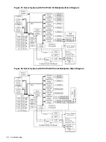
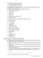
Two LBA chips use dual-rope (4 ropes total) interfaces (both are for customer use) to support
two single 64-bit PCI-X slots running at 133 MHz;
•
Two LBA chips use two quad-rope (8 ropes total) interfaces (both are for customer use) to
support two single 64-bit PCI-X slots running at 266 MHz.
Power Subsystem (BPS and I/O VRM)
The two bulk power supply CRUs shared by both the chassis provides N+1 redundancy for their
chassis. Each power supply CRU is identified by the chassis as 0 and 1 for logging purposes
only as there are no LEDs on the diagnostic LED panel for these external CRUs.
Power supply CRU failures are identified visually by a single green LED that is turned off when
one or both of the power supplies fail; logged as an IPMI event by voltage sensor logic; and
identified as a power supply CRU failure by the BMC turning on the appropriate LEDs on the
front LED panel.
The I/O VRM CRU, located beside the core I/O board CRU, provides all I/O subsystem dc power.
Power Subsystem Behavior
Each bulk power supply CRU provides 1600 Watts of dc power from a nominal 240 VAC 50-60
Hz. The baseboard management controller (BMC) chip located on the Unified Core I/O board
CRU controls the flow of +12 VDC power to the server’s CRUs.
NOTE:
You can control and display power supply status remotely with the iLO 2 MP
pc
and
ps
commands, respectively.
Typical power up sequence of the server is as follows:
•
Power LED on front panel glows steady Amber when one or two bulk power supplies are
plugged into nominal AC voltage and the +3.3 V dc housekeeping voltage comes on and
stays on whenever AC power is present.
•
The BMC, iLO 2 MP, Flash memory, and chassis intrusion circuits are reset after the +3.3
V dc housekeeping voltage stabilizes.
•
The BMC monitors the Power button on the front panel.
•
When the Power button is pressed or when a Wake-on-LAN (WOL) signal is asserted, the
BMC signals the bulk power supplies to fully power up.
•
+12 V dc comes up and all of the cooling fans and the various VRMs come up sequentially.
•
The BMC signals when the server is ready to come out of reset (clocks are programmed
and stable, etc.).
•
The server is brought out of reset.
•
The zx2 chip resets all components connected and the server begins the boot process.
Power LED/Switch
The front panel system power LED indicates the status of system power. It is incorporated inside
the Power button itself.
The Power button has a momentary switch (as opposed to a latching switch) that is recessed or
covered to prevent accidental activation/de-activation.
If the OS is up, pressing the Power button for less than four seconds results in a graceful shutdown
of the operating system and a subsequent removal of system power. Pressing the Power button
for greater than four seconds results in a hard shutdown (system power removed). While the
server is booting (before the system has passed
EFI_EXIT_BOOT_SERVICES
), the BMC will
power the server off immediately on a button press, since there is no concept of soft shutdown
in this state.
Power Subsystem (BPS and I/O VRM)
161

