SCSI and I/O 8-67
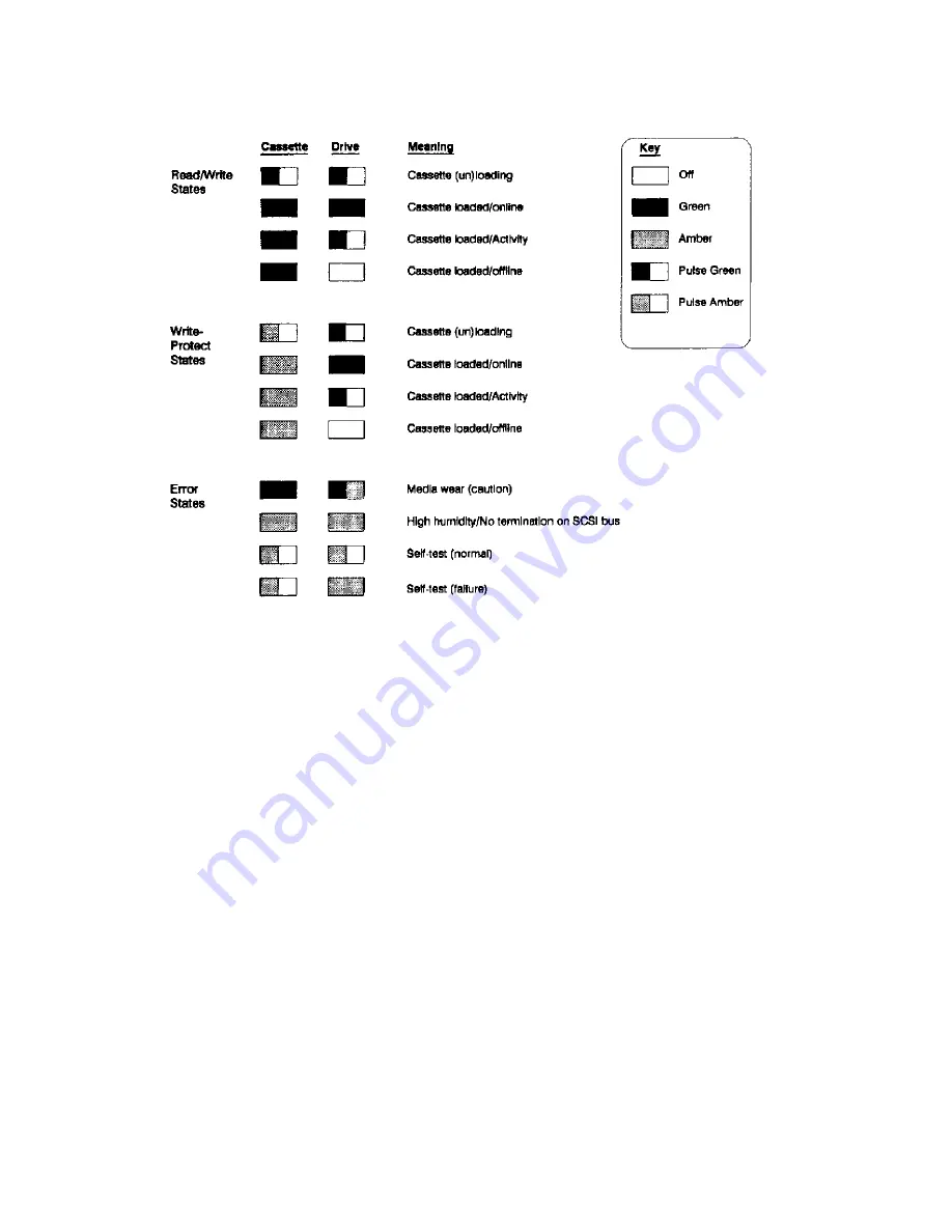
Figure 8-35. Cassette and Drive Light Definitions
Media wear (caution)
- indicates head cleaning is needed. This is an indication of an excessive number of
Read-After-Write (RAW) or third level error correction (C3 ECC) errors. This condition can be caused by
dirty heads or by a cartridge approaching the end of its life. If the flashing light reoccurs after the initial
cleaning, the data cartridge involved should be removed from use by reading the data from the tape and
copying that data to a new tape. The indication is only cleared by completing a cleaning cycle, no matter
what the cause is, however, the indication does not stop the activity of the tape unit.
Self-Test
- During power-on, the drive executes a self test diagnostic sequence. This is shown by both the
drive and cassette lights flashing yellow. If the self-test fails, the right Drive light shows a steady yellow
condition while the cassette light flashes yellow.
Forced Eject
There are some situations where the user’s depression of the eject button may not cause a cartridge to be
ejected within an acceptable time. For instance, the media surface may be badly damaged and the drive is
having trouble recovering data. Or, the cartridge may be of poor quality and has jammed one of its reels
which prevents it from turning. In these and many similar situations, the drive will usually invoke a series
of error recovery actions in an attempt to carry out the task it was given before the eject button was pressed.
As the normal eject request is queued by the drive until it has completed any pending operations (i.e.
flushing data from the buffer to tape, writing EOD, rewinding, etc.) some users may become frustrated at
the apparent lack of response to their depression of the eject button. For this reason, the Forced Eject feature
is provided. This allows the user to request the drive to immediately eject the cartridge regardless of any
operations outstanding or error recovery actions in progress.
Summary of Contents for 3000/9x9KS Series
Page 14: ...xiv Contents E Sources of Information on the Web ...
Page 28: ...2 8 Install and Configuration Figure 2 4 HP PB I O Slot Location Diagram Kx70 Kx80 ...
Page 44: ...2 24 Install and Configuration ...
Page 68: ...3 24 Troubleshooting HP 3000 Core I O Figure 3 4 HP 3000 Core I O ...
Page 120: ...5 6 Diagnostics ...
Page 128: ...6 8 Replaceable Parts Figure 6 4 Peripheral Bay Expanded View ...
Page 136: ...6 16 Replaceable Parts ...
Page 150: ...7 14 Removal and Replacement Figure 7 11 Peripheral Bay Rear View ...
Page 180: ...7 44 Removal and Replacement Figure 7 35 Cabinet Exploded View Rear ...
Page 209: ...SCSI and I O 8 21 Figure 8 3 A3629A ST19171WD J2 and J6 Jumper Settings ...
Page 217: ...SCSI and I O 8 29 Figure 8 7 A3353A source 2 J3 Jumper Positions ...
Page 218: ...8 30 SCSI and I O Figure 8 8 A3353A source 2 Option Connector Jumper Positions ...
Page 280: ...8 92 SCSI and I O Diagnostics CSTM SCSIDDS SYSMAP IOMAP ...
Page 298: ...8 110 SCSI and I O Diagnostics SCSICD IOMAP SYSMAP ...
Page 302: ...8 114 SCSI and I O ...
Page 308: ...Support Information B 2 HP 9x9KS Block Diagram Figure B 1 HP 3000 9x9KS Block Diagram ...
Page 309: ...B 3 Support Information HP K100 Block Diagram Figure B 2 HP 9000 K100 Block Diagram ...
Page 310: ...Support Information B 4 HP K2x0 K4x0 Block Diagram Figure B 3 HP 9000 K2x0 K4x0 Block Diagram ...
Page 311: ...B 5 Support Information Kx70 Kx80 Block Diagram Figure B 4 HP9000 Kx70 Block Diagram ...
Page 342: ...Memory Configuration Guidelines C 16 ...
Page 350: ...D 8 New System Features ...


