VideoBloX MODULES
26
SW1.8 SW1.7 SW1.6 SW1.5
SW1.4
SW1.3
SW1.2
SW1.1 Unit Address
Off Off Off Off Off Off Off Off
0-not
allowed
Off Off Off Off Off Off Off On
1
Off Off Off Off Off Off On Off
2
Off Off Off Off Off Off On On
3
Off Off Off Off Off On Off Off
4
Off Off Off Off Off On Off On
5
Off Off Off Off Off On On Off
6
Off Off Off Off Off On On On
7
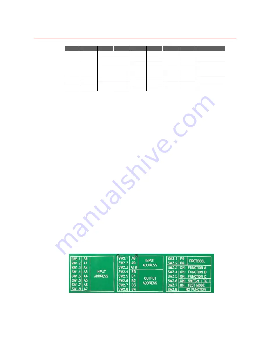
DIP Switch Settings of HVBM64
Figure 2-31
shows the DIP switch settings for the HVBM64 module.
•
DIP Switches S1 (1-8) and S2 (1-3) define the card’s address in a binary format
and is set to represent the camera range. For cameras 1-16, set the address to 1,
and cameras 17-32 set to 2, etc.
•
DIP Switch S2 (4-8) sets the monitor group in binary format. Each monitor group
contains 64 monitors. Setting S2 (4-8) to ”00000” means the input card should be
mounted in the chassis whose outputs range from 1 to 64. Setting S2 (4-8)
to ”100000” means the input card should be mounted in the chassis whose
outputs range 65-128.
Note:
This setting is relative to the output group address setting of the output
board. In one chassis all the input and output board should be set in the same
output group. Please refer to Page 12.
•
DIP Switch S3 (1-2) not used, set to off.
•
DIP Switch S3 (3-5): Only S3(3) has been implemented. When S3(3) is on,
replies will be muted. Used for systems that have 2 or more input cards with the
same address (e.g. systems with more than 64 outputs).
•
S3 (6) is used for testing to switch 16 cameras to the outputs. If the address is 1,
cameras 1-16 will be switched to monitors 1-16. If the address is 2, cameras 1-
16 will be switched to monitors 17-32, etc.
•
S3 (7) is a test mode that will randomly switch cameras to monitors. Used in
manufacturing.
•
S3 (8) is not used.
Note: For DIP switch, UP is 1 or ON, DOWN is 0 or OFF.
Figure 2-31 HVBM64 DIP SW Settings
Summary of Contents for VideoBloX
Page 1: ...800 04465 April 2008 Rev A VideoBloX Matrix Switcher User Manual ...
Page 2: ...Revision History ISSUES DATE REVISIONS A Apr 2009 Initial Release ...
Page 16: ......
Page 55: ...Honeywell 39 Figure 2 56 SW 3 and SW 4 settings for interlink input module ...
Page 163: ...Honeywell 147 ...
Page 179: ...Honeywell 163 Note Device key codes please refer to command DEVICE ...


