
Document No: C-61-00003-3
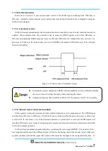
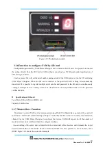
Figure 3-27 IP initialization switch
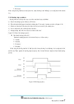
3.16 Function to configure UAM by SD card
Configuration generated by UAM Project Designer can be saved in the SD card. It is possible to transfer
the setting directly from the SD Card to UAM without connecting to a PC. Recommended specification of
SD card is given below.
Create a project file with set the serial number and password of the UAM and save it on the SD card using
UAM Project Designer. When the SD card is inserted to the specified UAM, settings are automatically
transferred. It is possible to register multiple serial number and password in the SD card to simultaneously
configure multiple devices. Setting will not be transferred to the unspecified UAM or if the password
verification fails.
Specification of SD card
Type: Micro SD card, Micro SDHC card
Capacity: 16GB or less
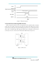
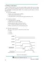
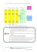
3.17 Master-Slave Function
Maximum 4 units of UAM can be interconnected using RS-485 for Master/slave operation. One unit will
function as a master unit communicating with up to 3 units that function as slaves via safety communication
channel
.
Use the UAM Project Designer to configure the devices. UAM will report error if the number of
master and slave units is different than the configured settings.
Area switching of the slave unit is linked with the master unit while the slave units transmit the object
detection information to the master which controls the OSSD. It is also possible to use each slave unit’s
OSSD. Figure 3-28 shows the connection example.
Summary of Contents for UAM-05LP
Page 1: ... Document No C 61 00003 3 ...
Page 104: ... Document No C 61 00003 3 Figure 7 33 b Function Figure7 33 c Area ...
Page 107: ... Document No C 61 00003 3 Figure 7 36 a Project report tab Figure 7 36 b Error report tab ...
Page 148: ... Document No C 61 00003 3 13 External dimension 13 1 UAM 05LP ...
Page 149: ... Document No C 61 00003 3 13 2 Base mounting bracket ...
Page 150: ... Document No C 61 00003 3 13 3 Rear mounting bracket ...
Page 151: ... Document No C 61 00003 3 13 4 Cover Protection Bracket ...
Page 152: ... Document No C 61 00003 3 14 EC Declaration of conformity ...
Page 153: ... Document No C 61 00003 3 ...


