
Document No: C-61-00003-3
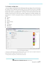
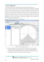
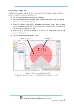
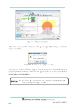
Figure 7-48
Muting zone configuration example 2
Muting zone configuration example as square is drawn from point 1 to point 2
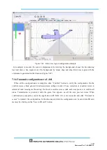
7.15.4
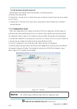
Reference region configuration
Follow the steps below to configure reference region.
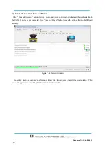
Ensure the UAM is firmly mounted at its location.
Ensure the connection between the UAM and PC.
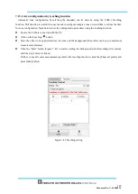
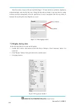
Click the Function tab and enable the Reference Monitor function and enter the required tolerance
distance (default 100mm).
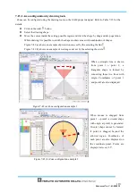
Click the Area tab.
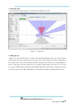
Main screen displays the configuration for reference region (Figure 7-49)
.
First area on the preview
indicated by “REF” represents the reference area.
Configure the
reference region by using the drawing tools. Move the cursor on the drawing panel
and drag and drop to configure the reference. Monitoring region is displayed in green
Protection zone
Muting zone
1
2
Summary of Contents for UAM-05LP
Page 1: ... Document No C 61 00003 3 ...
Page 104: ... Document No C 61 00003 3 Figure 7 33 b Function Figure7 33 c Area ...
Page 107: ... Document No C 61 00003 3 Figure 7 36 a Project report tab Figure 7 36 b Error report tab ...
Page 148: ... Document No C 61 00003 3 13 External dimension 13 1 UAM 05LP ...
Page 149: ... Document No C 61 00003 3 13 2 Base mounting bracket ...
Page 150: ... Document No C 61 00003 3 13 3 Rear mounting bracket ...
Page 151: ... Document No C 61 00003 3 13 4 Cover Protection Bracket ...
Page 152: ... Document No C 61 00003 3 14 EC Declaration of conformity ...
Page 153: ... Document No C 61 00003 3 ...


