

Document No: C-61-00003-3
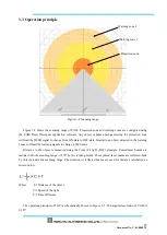
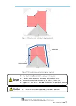
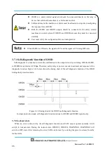
Figure 3-9 Warning zones
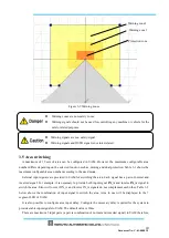
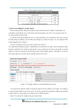
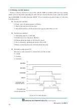
3.5 Area switching
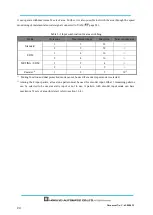
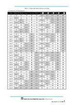
A maximum of 32 sets of area can be configured in UAM. However the maximum configurable area
number differs depending on the selected function such as, muting and dual protection. Table 3-1 shows the
maximum configurable area number according to the used mode.
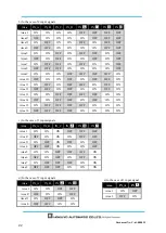
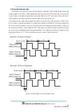
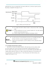
External input signals are provided in UAM for switching the area. Each signal has a pair of normal and
inverted signal. For example, it is necessary to provide both input signal
IN_A
and inverse
IN_A
signal to
switch the area. Error will occur if IN_A and inverse IN_A signals do not complement each other. Table 3-2
below shows the combination of input signal to switch the area. Area in use will be displayed in the 7
segment LED of UAM.
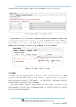
It is also possible to configure area input delay. Configure the necessary delay required for the system to
provide stable input signals to UAM. The default value is 30ms.
There are maximum 5 input pairs (a pair is combination of normal and inverted signal) in UAM therefore,
Warning zones are non-safety zones.
Warning signals should not be used for controlling any machine or vehicle for the
safety-related purposes.
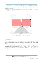
Protection zone
Warning zone 1
Warning zone 2
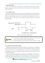
Warning signals are non safety-signal.
Warning signals and OSSD signal is not inter-related.
Summary of Contents for UAM-05LP
Page 1: ... Document No C 61 00003 3 ...
Page 104: ... Document No C 61 00003 3 Figure 7 33 b Function Figure7 33 c Area ...
Page 107: ... Document No C 61 00003 3 Figure 7 36 a Project report tab Figure 7 36 b Error report tab ...
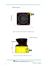
Page 148: ... Document No C 61 00003 3 13 External dimension 13 1 UAM 05LP ...
Page 149: ... Document No C 61 00003 3 13 2 Base mounting bracket ...
Page 150: ... Document No C 61 00003 3 13 3 Rear mounting bracket ...
Page 151: ... Document No C 61 00003 3 13 4 Cover Protection Bracket ...
Page 152: ... Document No C 61 00003 3 14 EC Declaration of conformity ...
Page 153: ... Document No C 61 00003 3 ...


