
Document No: C-61-00003-3
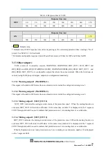
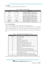
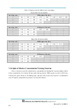
Table 3-4 Response time of UAM
OFF
Response time (ms)
60
90
120
150
180
210
240
270
300
330
360
390
420
450
480
510
ON
Response time (ms)
270
300
330
360
390
420
450
480
510
*
Default value
* Default value of OFF response time varies depending on the selected application when creating a “New”
project. See Table 4-11 for the details.
*
Minimum configurable response time in Master/Slave mode is 120ms for OFF and 300ms for ON.
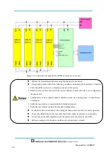
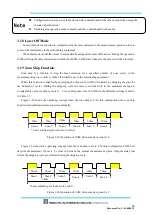
3.13 Other outputs
UAM consist of 6 non-safety outputs, WARNING1, WARNING2, MUT_OUT1, MUT_OUT2 and
RES_REQ1 and RES_REQ2. WARNING1/OSSD3, WARNING2/OSSD4, RES_REQ1/ MUT_OUT1 and
RES_REQ2/ MUT_OUT2
are configurable outputs that share the same terminal. When the functions are
selected using UAM project designer, outputs are configured automatically.
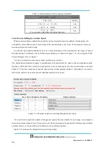
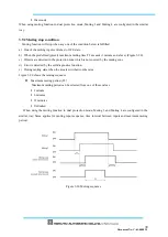
3. 13.1 Warning output 1 (WARNING 1)
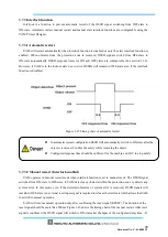
This signal will switch to OFF-state when an obstacle is detected in the configured warning zone 1.
3. 13.2 Warning output 2 (WARNING 2)
This signal will switch to OFF-state when an obstacle is detected in the configured warning zone 2.
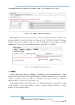
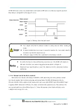
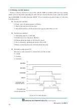
3. 13.3 Muting output 1 (MUT_OUT 1)
MUT_OUT1 indicates the muting/override status of the protection zone 1. When the muting function is
activated, MUT_OUT1 will switch to ON-state. At the same time, number 37 is displayed on the 7-segment
LED. This signal should be used to indicate that protection zone 1 is in muting state or override state.
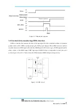
3. 13.4 Muting output 2 (MUT_OUT 2)
MUT_OUT2 indicates the muting/override status of the protection zone 2.When the muting function is
activated, MUT_OU2 will switch to ON-state. At the same time, number 38 is displayed on the 7-segment
LED. This signal should be used to indicate that protection zone 2 is in muting state or override state.
When both protection zone 1 and protection zone 2 are in muting or override state, number 39 is displayed
on the 7-segment LED.
Summary of Contents for UAM-05LP
Page 1: ... Document No C 61 00003 3 ...
Page 104: ... Document No C 61 00003 3 Figure 7 33 b Function Figure7 33 c Area ...
Page 107: ... Document No C 61 00003 3 Figure 7 36 a Project report tab Figure 7 36 b Error report tab ...
Page 148: ... Document No C 61 00003 3 13 External dimension 13 1 UAM 05LP ...
Page 149: ... Document No C 61 00003 3 13 2 Base mounting bracket ...
Page 150: ... Document No C 61 00003 3 13 3 Rear mounting bracket ...
Page 151: ... Document No C 61 00003 3 13 4 Cover Protection Bracket ...
Page 152: ... Document No C 61 00003 3 14 EC Declaration of conformity ...
Page 153: ... Document No C 61 00003 3 ...


