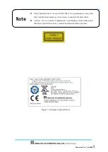

Document No: C-61-00003-3
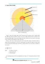
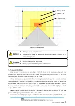
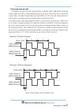
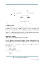
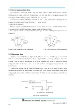
In the explanation above, the transfer method of the rotation was based on the frictional wheel. Same
method can be applied for other cases to estimate the pulse count generated for one rotation of the
wheel.
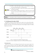
3.6.2 Recommend incremental encoder specification
・
Phase setting 90° dual channel rotary encoder
・
Power supply: DC 24V
・
Output : Complementary output
・
Protective class : IP 54 or more
・
Output cable : Twist pair/ shield cable
・
Maximum pulse frequency : 100 kHz
・
Minimum pulse frequency : 50 pulse/cm
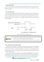
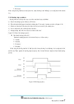
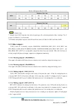
3.6.3 Tolerances allowed for encoder
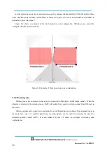
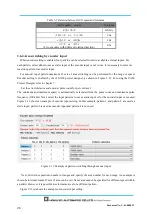
When AGV travels in a forward direction, speed input through the two incremental encoders will be same
as the original pulse frequency. However, there are cases when two speed input values may differ, such as
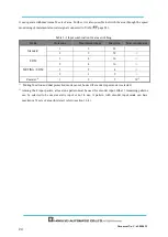
while cornering and due to AGV tire exhaustion. The
difference between two input speeds should not exceed
the error tolerance for more than a fixed period of time. Set the error tolerance in the range of 0 to 80%.
Of the two speeds, the larger value will be considered for vehicles speed calculation. When permitted error
tolerance exceeds the fixed period OSSD will go to OFF state. Tolerance period differs according to the
vehicle speed as shown in table 3-3.
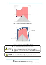
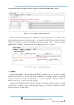
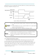
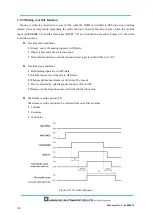
User should verify the proper area switching through encoder inputs.
Always use 2 units of incremental encoder. It is not possible to detect the failure of
incremental encoder or abnormal travel of the vehicle with single unit.
Use separate sets of cable to connect outputs from incremental encoder 1 and 2 to the
respective encoder input terminals of UAM.
Separate the power supply cables and power source of each incremental encoder. Output
pairs of Encoder connection should match the input pair of UAM.
Do not wire other power lines parallel to encoder and UAM or wire in the same duct. There
is a possibility of noise disturbance.
Summary of Contents for UAM-05LP
Page 1: ... Document No C 61 00003 3 ...
Page 104: ... Document No C 61 00003 3 Figure 7 33 b Function Figure7 33 c Area ...
Page 107: ... Document No C 61 00003 3 Figure 7 36 a Project report tab Figure 7 36 b Error report tab ...
Page 148: ... Document No C 61 00003 3 13 External dimension 13 1 UAM 05LP ...
Page 149: ... Document No C 61 00003 3 13 2 Base mounting bracket ...
Page 150: ... Document No C 61 00003 3 13 3 Rear mounting bracket ...
Page 151: ... Document No C 61 00003 3 13 4 Cover Protection Bracket ...
Page 152: ... Document No C 61 00003 3 14 EC Declaration of conformity ...
Page 153: ... Document No C 61 00003 3 ...


