


SYSTEM / Control System
T2-1-2
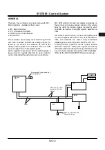
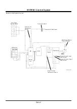
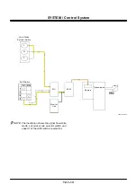
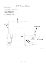
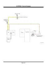
MC, ECM and Monitor Unit are used for various op-
eration controls of the body.
•
The analog input signals from the sensors and
switches attached to devices other than the engine
and monitor unit as well as the analog output signals
from the solenoid valves are transmitted to MC, and
converted into the digital signals to be uploaded on
CAN.
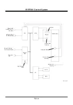
•
The analog input signals from the sensors attached
to the engine are transmitted to ECM, and converted
into the digital signals to be uploaded on CAN.
•
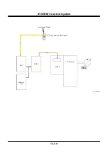
The analog input signals from the cab, and the
analog input signals from the sensors and switches
necessary for indication of the monitor are trans-
mitted to the monitor unit, and converted into the
digital signals to be uploaded on CAN.
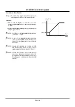
Each controller detects lacking information necessary
for the control program from the CAN data. (digital
signals)
Each controller makes various control program arith-
metic operations by using the detected data (digital
signals), outputs the actuation signals to the solenoid
valves unit and torque control solenoid valve, and
controls the pump, engine, transmission and valves.
The analog signals from various sensors, switches
and solenoid valves are periodically transmitted to
each controller, and converted into the digital signals
to be uploaded on CAN.
By repeating the above operations, the vehicle body
movement is watched and controlled.
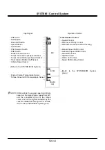
Summary of Contents for ZW180
Page 1: ......
Page 2: ......
Page 8: ...4GDT 1 2 Blank ...
Page 10: ...GENERAL Specification T1 1 2 Blank ...
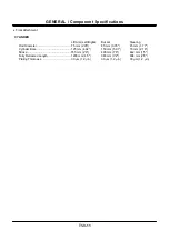
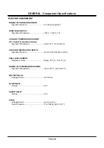
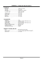
Page 38: ...GENERAL Component Specifications T1 3 14 Blank ...
Page 39: ...MEMO ...
Page 40: ...MEMO ...
Page 42: ...4GDT 2 2 Blank ...
Page 56: ...SYSTEM Control System T2 1 14 Blank ...
Page 82: ...SYSTEM Control System T2 1 40 Blank ...
Page 92: ...SYSTEM Control System T2 1 50 Blank ...
Page 106: ...SYSTEM Control System T2 1 64 Blank ...
Page 116: ...SYSTEM ECM System T2 2 10 Blank ...
Page 128: ...SYSTEM Hydraulic System T2 3 12 Blank ...
Page 147: ...SYSTEM Hydraulic System T2 3 31 Blank ...
Page 150: ...SYSTEM Hydraulic System T2 3 34 Blank ...
Page 184: ...SYSTEM Electric System T2 4 34 Blank ...
Page 185: ...MEMO ...
Page 186: ...MEMO ...
Page 195: ...COMPONENT OPERATION Pump Device T3 1 7 Blank ...
Page 212: ...COMPONENT OPERATION Control Valve T3 2 4 T4GB 03 02 003 1 2 3 4 5 7 8 9 10 11 7 6 ...
Page 214: ...COMPONENT OPERATION Control Valve T3 2 6 T4GB 03 02 003 1 2 3 4 5 7 8 9 10 11 7 6 ...
Page 226: ...COMPONENT OPERATION Control Valve T3 2 18 Blank ...
Page 232: ...COMPONENT OPERATION Control Valve T3 2 24 Blank ...
Page 248: ...COMPONENT OPERATION Steering Pilot Valve T3 4 6 Blank ...
Page 258: ...COMPONENT OPERATION Steering Valve T3 5 10 Blank ...
Page 274: ...COMPONENT OPERATION Pilot Valve T3 6 16 Blank ...
Page 282: ...COMPONENT OPERATION Pilot Valve T3 6 24 Blank ...
Page 299: ...COMPONENT OPERATION Ride Control Valve T3 8 5 Blank ...
Page 306: ...COMPONENT OPERATION Ride Control Valve T3 8 12 Blank ...
Page 348: ...COMPONENT OPERATION Drive Unit T3 9 42 Blank ...
Page 371: ...MEMO ...
Page 372: ...MEMO ...
Page 374: ......


