


SYSTEM / Hydraulic System
T2-3-22
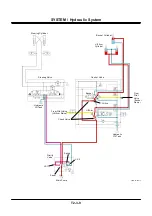
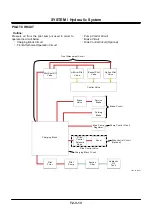
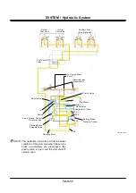
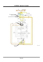
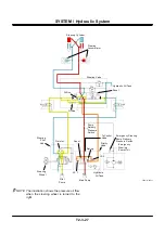
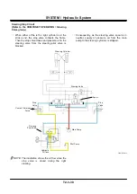
Brake Circuit
Service Brake Circuit
(Refer to the COMPONENT OPERATION /
Charging Block group.)
(Refer to the COMPONENT OPERATION / Brake
Valve group.)
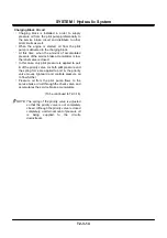
•
Pressure oil from the pilot pump flows through the
charging block, and is accumulated in the service
brake accumulators.
•
By stepping the brake pedal, pressure in the
service brake accumulators is applied to the front
brake and the rear brake through the brake valve,
and actuates the service brake.
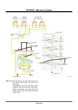
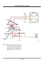
•
When the brake pedal is stepped several times,
pressure inside the service brake accumulators is
lowered, and the relief valve is closed.
•
The priority valve spool moves rightward, and
pressure in the service brake accumulators is
kept constant by preferentially supplying pressure
oil from the pilot pump to the service brake circuit,
and firmly brakes the vihicle.
NOTE: The spring of the priority valve is adjusted
so that the priority valve is not completely
closed. Although the priority valve is closed
completely, a certain amount of pressure oil
is being supplied to the circuits
downstream.
NOTE: Although the engine is stopped, the service
brake circuit pressure is retained for a while
due to the functions of the service brake
accumulators and the check valve.
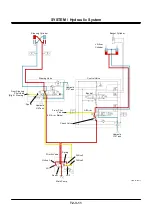
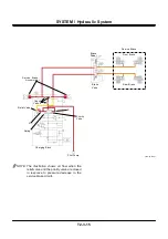
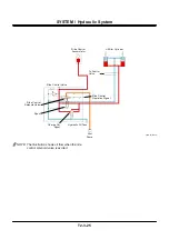
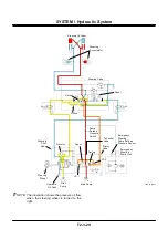
Parking Brake Circuit
•
Pressure oil from the pilot pump is applied to the
parking brake solenoid valve in the charging
block.
•
When the parking brake is turned OFF, the
parking brake solenoid valve is excited, and
pressure oil entering the parking brake cylinder
releases the parking brake.
•
If the parking barke is turned ON, the parking
brake solenoid valve is unexcited, and pressure
oil stops supplying to the parking brake. Therefore
the parking brake is applied.
•
Although pressure is lowered caused by damage
of hose or something in the upstream of the
parking brake solenoid valve, pressure for parking
brake circuit is maintained for a while by the pilot
accumulator.
NOTE: The parking brake is released when the
solenoid valve is excited.
Summary of Contents for ZW180
Page 1: ......
Page 2: ......
Page 8: ...4GDT 1 2 Blank ...
Page 10: ...GENERAL Specification T1 1 2 Blank ...
Page 38: ...GENERAL Component Specifications T1 3 14 Blank ...
Page 39: ...MEMO ...
Page 40: ...MEMO ...
Page 42: ...4GDT 2 2 Blank ...
Page 56: ...SYSTEM Control System T2 1 14 Blank ...
Page 82: ...SYSTEM Control System T2 1 40 Blank ...
Page 92: ...SYSTEM Control System T2 1 50 Blank ...
Page 106: ...SYSTEM Control System T2 1 64 Blank ...
Page 116: ...SYSTEM ECM System T2 2 10 Blank ...
Page 128: ...SYSTEM Hydraulic System T2 3 12 Blank ...
Page 147: ...SYSTEM Hydraulic System T2 3 31 Blank ...
Page 150: ...SYSTEM Hydraulic System T2 3 34 Blank ...
Page 184: ...SYSTEM Electric System T2 4 34 Blank ...
Page 185: ...MEMO ...
Page 186: ...MEMO ...
Page 195: ...COMPONENT OPERATION Pump Device T3 1 7 Blank ...
Page 212: ...COMPONENT OPERATION Control Valve T3 2 4 T4GB 03 02 003 1 2 3 4 5 7 8 9 10 11 7 6 ...
Page 214: ...COMPONENT OPERATION Control Valve T3 2 6 T4GB 03 02 003 1 2 3 4 5 7 8 9 10 11 7 6 ...
Page 226: ...COMPONENT OPERATION Control Valve T3 2 18 Blank ...
Page 232: ...COMPONENT OPERATION Control Valve T3 2 24 Blank ...
Page 248: ...COMPONENT OPERATION Steering Pilot Valve T3 4 6 Blank ...
Page 258: ...COMPONENT OPERATION Steering Valve T3 5 10 Blank ...
Page 274: ...COMPONENT OPERATION Pilot Valve T3 6 16 Blank ...
Page 282: ...COMPONENT OPERATION Pilot Valve T3 6 24 Blank ...
Page 299: ...COMPONENT OPERATION Ride Control Valve T3 8 5 Blank ...
Page 306: ...COMPONENT OPERATION Ride Control Valve T3 8 12 Blank ...
Page 348: ...COMPONENT OPERATION Drive Unit T3 9 42 Blank ...
Page 371: ...MEMO ...
Page 372: ...MEMO ...
Page 374: ......


